

Introduction: Eclips3D - High Precision 3D Printer


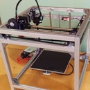
This is it! The fully open-sourced printer to trump all others, and at a fraction of the cost. Let's not waste any time! For files, info, and parts to purchase, visit my website here!
If you have any questions about the assembly or post assembly, try checking the forums for the answer:
http://eclips3d.proboards.com/
Official Eclips3D Quickstart Guide
https://www.instructables.com/id/Eclips3D-Quick-Sta...
Let's get building!
DISCLAIMER:
The final product will vary based on your individual assembly. As this product requires you to source and build a good portion of the printer, I am not responsible if the end result does not meet what is claimed here. However, if you follow the BOM and these assembly instructions exactly, you should have no problem achieving incredibly high quality prints!
Step 1: Before Getting Started
The Eclips3D is certainly not made to be a beginners 3D printer. It is designed for people who are familiar with 3D printing and have used 3D printers before. It also may require a bit of work after it is assembled to dial everything in, since the printer is a kit and each person's assembly may be a little different. However, if you put the time in and follow the directions exactly, you will end up with an amazing 3D printer which rivals the speed, quality, quietness, and aesthetics of the Ultimaker 2 or similar. Ok fine, it doesn't look quite as good, but it's not bad for a DIY 3D printer!
After completing the build, head over to the quickstart guide here to get up and running as easily as possible!
Important note: In these assembly pictures you may see red 3D printed pieces instead of cnc'd aluminum plates. This was due to a lack of the plates at the time I made the assembly instructions. In the final printer, you MUST use aluminum plates. If you do not, the quality of your prints will suffer.
Step 2: Gathering Materials
Here's the fun part, gathering everything you need. Luckily, the number of custom machined parts is relatively minimal. This should allow most people to be able to gather and build this printer on their own.
Here you can find the official BOM with everything you will need to make the printer.
http://www.eclips3d.com/docs.html
Please only make substitutions if you know what you are doing and you understand how the parts will be needed in the design. If you don't, I would recommend sticking to what I recommend unless you find the same product from another online retailer.
Step 3: Preparing Printed Parts


Before you begin, it is good to get the printed parts all ready to go. This step will take a little bit of time, but not nearly as much as it did for my old printer so no complaining!
Wherever you see a square hole or slot in plastic pieces, a square M3 nut will go in that place. Make sure the hole in the square nut lines up with the holes in the plastic parts. It is highly recommended that you superglue these nuts in place so the parts are easier to work with, especially the one in the bottom of part A1 as seen in the last picture.
Clean off any support or loose material you may see. Depending on the printer used to make these parts will depend on how many loose strands you have and where they are! A high quality printer should make parts with few to none.
Finally, you will need to insert bushings into some plastic parts. Depending on the quality of the printed parts, this may require some additional cleaning and work to get right. You will need to insert 2x part "G8 - M10 Oil Free Bushing" into each of the two parts "A15 - Y Bearing Block". Additionally, you will need to insert 4x of the same bushings into part "A1 - X Gantry Main". See the pictures for reference.
After that, you're pretty much ready to go!
Step 4: Identifying Parts


With a printer this complex, there are a whole mess of parts that go into it! Just looking at the BOM may not be enough, so here is just a breakdown of all the different parts in the printer, each one labeled with a note declaring its part number.
Note: Take special note as to bolt lengths. Because the printer is rather complex, there are a variety of different bolt sizes and lengths and you do not want to get these mixed up!
Step 5: Assembling the Frame
The frame is one of the more difficult parts, but only because the assembly isn't quite as easy as the rest because of the open slot extrusions! However, using the spacer tool from the printed set (and acrylic panels if you have them) will make the assembly and alignment a whole lot easier!
To assemble, watch the following 3 videos in order!
Step 6: E3D Hot End Assembly

In this step, you will be assembling your E3D V6 12v direct drive hot end. If you purchased a different hot end, assemble your hot end according to it's directions. Just remember this printer was designed around the E3D so using a different hot end will make things much more complicated!
Note that you can substitute the E3D V6 for the E3D V6 lite without modifying parts, but the hot end performance will not be as good.
To assemble, reference the official E3D assembly guide and/or this video by Tom
Step 7: Adding Motor Mounts


Parts Needed
1x A9 - Rod Bracket BL
1x A10 - Rod Bracket BR
2x B2 - XY Motor Plate
4x D10 - M5x8
6x D11 - M5x10
2x G18 - Pre AssemblyT Nuts
Assembly
1. Secure part B2 to back right corner of frame. Align 2x pre-existing T-Nuts with holes on B2. Use 2x D10 to secure plate to frame, do not tighten.
2. Align 2x pre-existing T-Nuts with holes on other side of B2.
3. Align and place part A10 over part B2. Use 2x D11 to secure parts together.
4. Tighten down the 4 bolts added in the first 3 steps.
5. Lay the printer on its back side. Slide 1x part G18 and align with hole in back of A10. Insert part D11 but DO NOT TIGHTEN YET.
6. Repeat steps 1-5 for the back left side, but use part A9 instead of part A10.
Step 8: Adding Left Idler Bracket


Parts Needed
1x A11 - Rod Bracket FL
1x B1 - Bearing Plate
1x D10 - M5x8
2x D11 - M5x10
1x D12 - M5x14
1x D14 - M5x25
3x D15 - M5 Washer
1x G3 - 6mm M5 Aluminum Spacer
4x G11 - F625zz Bearing
1x G18 - Pre AssemblyT Nuts
Assembly
1. Secure part B1 to the front left of the frame using 1x part D10 to a rep-existing t-nut. Ensure no other t-nuts are trapped to the left of the one used. Do not tighten.
2. Create this sub-assembly using part D14 for the main bolt. Stack 2x part G11 facing each other first, to make a pulley guide. Then, add 2x part D15 and part G3 to the bolt.
3. Align hole in part B1 with a pre-existing t-nut. Insert and secure sub-assembly from step 2. Do not tighten.
4. Build the sub-assembly using part D12 for the main bolt. Again, stack 2x part G11 to create the idler, then stack 1x part D15 to the end.
5. Bolt sub assembly from step 4 into threaded hole on bracket B1.
6. Place part A11 on top of plate B1. Align holes in A11 and B1 with a pre-existing t-nut. Insert and secure using 1x part D11. Tighten this bolt and the bolt and stack from steps 1 and 3.
7. Lay printer on front face. Insert 1x part G18 and align with hole in A11. Insert 1x part D11 into hole. DO NOT TIGHTEN.
8. This step is complete. Ensure all bolts except for the one from step 7 are tightened down snugly.
Step 9: Adding Right Idler Bracket


Parts Needed
1x A12 - Rod Bracket FL
1x B1 - Bearing Plate
1x D10 - M5x8
2x D11 - M5x10
1x D13 - M5x20
1x D14 - M5x25
6x D15 - M5 Washer
1x G3 - 6mm M5 Aluminum Spacer
4x G11 - F625zz Bearing
1x G18 - Pre AssemblyT Nuts
Assembly
1. Secure part B1 to the front right of the frame using 1x part D10 to a rep-existing t-nut. Ensure no other t-nuts are trapped to the right of the one used. Do not tighten.
2. Create this sub-assembly using part
3. Align hole in part B1 with a pre-existing t-nut. Insert and secure sub-assembly from step 2. Do not tighten.
4. Build the sub-assembly using part
5. Bolt sub assembly from step 4 into threaded hole on bracket B1.
6. Place part A12 on top of plate B1. Align holes in A12 and B1 with a pre-existing t-nut. Insert and secure using 1x part D11. Tighten this bolt and the bolt and stack from steps 1 and 3.
7. Lay printer on front face. Insert 1x part G18 and align with hole in A12. Insert 1x part D11 into hole. DO NOT TIGHTEN YET.
8. Grab 2x part C2 (used only for alignment) and place on the printer as shown. Note the tabs on the top of the plastic corner piece which should hold the extrusions in place.
9. Loosen any bolts necessary in order to slide the top frame square down to be flush with the top of the vertical extrusions, as seen in the photo. Tighten down all bolts to secure the frame in place.
10. Ensure all bolts are tightened down firmly. Don't forget the bolts connecting the plastic parts to the vertical extrusions and the bolts from previous steps.
Step 10: Adding X/Y Motors


Parts Needed
8x D1 - M3x8
2x E2 - Nema 17 1.7A
2x G7 - Neoprene Motor Damper
Assembly
1. Peel paper backing from parts G7. If you purchased the materials yourself from Misumi, you will need to cut out a piece that will fit on the face of a Nema 17 stepper motor. This does not have to be exact.
2. Apply parts G7 to plate B2 (xy motor plate). One damper on each side. Ensure bolt holes line up, if not you may use a small screwdriver or allen wrench to puncture new holes through the damper.
3. Align 1x part E2 with plate B2. Note orientation of wire socket. Insert 4x part D1 and screw into part E2. Snug up all 4 bolts first, then tighten going in a cross pattern. Ex. Tighten the back left, then the front right, then back right, then front left. Repeat until all 4 bolts are equally tight.
4. Repeat process for the 2nd part E2 on the left. Again, take note of the socket orientation and be sure to tighten bolts evenly.
Step 11: Adding Motor Pulleys


Parts Needed
2x G10 - 20t GT2 pulley
Assembly
1. Ignore top extrusions, you will not have those installed yet. The pictures were taken out of order. Simply loosen the two grub screws in parts G10.
2. Install 1x part G10 in orientation shown on left stepper motor. Blue Loctite is HIGHLY recommended on the grub screws, however you may not want to apply the Loctite until later if you want to ensure your alignment is correct before securing it in place. Tighten one grub screw aligned with the slot first. While tightening, twist the pulley very slightly back and forth to ensure the pulley is fully settled with the grub screw in the slot. Then, tighten the second grub screw. Do not overtighten. This little buggers have a habit of stripping out very easily. Leave about 1-2mm of the stepper shaft exposed, but this can be adjusted later if need be.
3. Repeat the process for the other stepper motor, but take note that on the right side, part G10 is installed "upside down" compared to the left side. Again, leave about 1mm of the shaft exposed and Blue Loctite is recommended on the grub screws.
Step 12: Adding Top Frame


Parts Needed
4x C2 - Horizontal Top Extrusion
4x C4 - Corner Bracket
4x D11 - M5x10
4x D12 - M5x14
4x D15 - M5 Washer
13x G18 - Pre Assembly T Nut
Assembly
1. Insert parts G18 into slots of extrusions C2 as shown. There are no T-nuts in the slots not shown. Take note of the missing T-nut in the 2nd extrusion from the top as shown in picture 2. Ensure 3 nuts are in this extrusion.
2. Install 2x parts C2 with T-Nuts installed as shown. The extrusion on the left should have 3 T-Nuts, while the one on the right should have 2. In both cases, the T-Nuts will be facing in toward the printer, not down.
3. Prepare 4x part D12 by inserting 1x part D15 onto each.
4. Prepare 4x part C4 by inserting sub-assemblies from step 3 into the hole shown. Be sure you are putting the bolts in the correct hole. It will be the same position hole for all 4 brackets.
5. Align a t-nut from each extrusion part C2 just installed with the holes in the plastic parts. Align sub-assemblies from step 4 against plastic extrusions, push existing bolts through and snug against extrusions C2.
6. Do this for all 4 corners.
7. Align last 2x part C2 with t-nuts as shown in final 2 pictures. The extrusion towards the front of the printer will have 2 T-Nuts facing in, and the back extrusion will have 6 T-Nuts facing in. Again, no T-Nuts should be facing down. Align extreme T-Nuts from each extrusion with the newly installed brackets from step 5-6. Insert 4x part D11 to secure extrusions in place.
8. Tighten all 8 newly installed bolts.
Step 13: Y Slider Assembly Part A


Parts Needed
2x A15 - Y Bearing Block
2x B4 - Y Axis Plate
8x D1 - M3x8
4x D8 - M3 Square Nut
Assembly
1. Align parts A15 with plates B4 as shown. Take note of the orientation of holes in part B4 as this piece is not symmetrical.
2. Insert 4x part D1 through holes in A15 and tighten for both sub-assemblies.
3. Flip parts over and insert 4x parts D8 into slots as shown.
4. Insert 4x part D1 through holes in side of parts A15 and tighten on just installed square nuts.
Step 14: Y Slider Assembly Part B


Parts Needed
2x Assemblies from step 11
2x D12 - M5x14
2x D14 - M5x25
12x D15 - M5 Washer
2x G3 - 6mm M5 Aluminum Spacer
8x G11 - F625zz Bearing
Assembly
1. Assemble the four idler stacks. The top two are identical and the bottom two are identical. The top two use parts D14 as the base bolt. Notice the error, there should be 2x part D15 above the two bearings (G11) and 3x part D15 below. The bottom two idlers use parts D12 as the base bolt and have 2x part G11 for the idler and 1x part D15 below.
2. Attach the idlers to the assemblies from the previous step. Take note where the stacks are in relation to the slotted holes on the metal plates.
Step 15: Adding Y Sliders


Parts Needed
2x Assemblies from step 12
2x A13 - Rod Clamp B
2x A14 - Rod Clamp F
2x G5 - 335mm M10 Hardened Shaft
2x D2 - M3x16
6x D3 - M3x20
8x D8 - M3 Square Nut
Assembly
1. Slide part G5 into assembly from previous step. Note this is the side with the small idler stack closer to the slotted holes, as seen in the picture.
2. Insert rod G5 into the front hole in the plastic bracket on the printer. It should be a snug fit.
3. Pivot the rod so the back sits flush in the back plastic bracket. The rod should be in fully now.
4. Insert 4x parts D8 into the back side of the plastic blocks. 2x of the parts go in each block.
5. Prepare plastic parts A13 and A14 by inserting parts D2 and D3 into them as shown in the picture.
6. Insert part A14 into the holes on the front plastic block to secure rod in place. Tighten but do not overtighten. Note the larger side of the piece faces up.
7. Insert part A13 into back plastic block to secure rod in place. Tighten but do not overtighten. Ensure rod is held securely in place.
8. Repeat steps 1-3 and steps 6-7 for the other side of the printer using the other assembly from the previous step.
Step 16: Adding X Slider


Parts Needed
1x A1 - X Gantry Main
3x A16 - Y Rod Clamp
1x A17 - Y Rod Clamp Trigger
16x D2 - M3x16
16x D8 - M3 Square Nut
2x G5 - 335mm M10 Hardened Shaft
Assembly
1. First, ensure you properly prepared part A1. For now, you should have the 4 bushings inserted and the one square nut (D8) inserted from the underside of the part. Also, prepare parts A16 and A17 by removing the thin walls located along the four square cuts on each piece, these thin walls are only for printing and you dont need them.
2. Insert both parts G5 through part A1. Then, slide clamps A16 and A17 onto the ends of the rods as shown. Pay careful attention to where part A17 is as it is different from the other 3 parts.
3. Align this subassembly over the two y sliders previously installed on the printer. Use one or two of parts D2 and D8 to hold the subassembly in place. Insert bolt D2 from the underside and part D8 wills it in a slot on top of the rod clamp.
4. Now, insert the rest of parts D2 and D8, the same as before, but do not tighten any of them down yet.
5. Slide the y gantry to the front max of the machine, then tighten down the four bolts on the front clamp on each side. This should secure the front rod in place and should make the gantry a bit more rigid.
6. This part is tricky. If you notice, the back rod can move forward and back a few mm. This is intentional to compensate for not all 3D printers making the printed parts exactly the same. By sliding the x slider back and forth, you'll notice it will force the rod to align with the carriage. What you want to do is tighten the bolts for this back rod in such a way that there is almost always a little bit of tension or resistance on the x slider. There is no exact way to do this, so you may have to adjust it a few times. You don't want it to be really tight at the end, but just a bit of resistance. The point of this is to reduce noise and increase quality by keeping tighter specs on the printer, if you are confused post a question or thread on the Eclips3D forums!
Step 17: Z Gantry Assembly


Parts Needed
1x B5 - Z Axis Plate
8x D9 - M4x8
2x D10 - M5x8
1x G2 - M8 Nut Plate
2x G9 - M10 Flanged Linear Bearing
Assembly
1. Gather parts. Flip part B5 upside down (direction may not matter depending on who you sourced your parts from).
2. Align part G2 with the center hole. Insert 2x bolts D10 through holes and tighten in threads of part B5. Do not overtighten or it may cause motion issues!
3. Insert parts G9 into the remaining 2 large holes. Note orientation of these parts, the side with the larger holes for the bolt heads should be facing up.
4. Insert 4x parts D9 into each linear bearing and tighten in threads of part B5. Make these very tight.
Step 18: Incorporating Z Axis


Parts Needed
1x Z Gantry Assembly from step 15
8x D10 - M5x8
4x G19 - SK10 Shaft Support
2x G6 - 360mm M10 Hardened Shaft
Assembly
1. Attach 2x part G19 to the bottom back rail of the frame using 4x bolts D10 and the pre-existing T-Nuts in these extrusion slots. It is recommended you fasten the parts such that the black set screws are facing outwards. This will make tightening the bolts easier later on.
2. Attach 2x part G19 to the top back rail of the frame using 4x bolts D10 and the pre-existing T-Nuts in these extrusion slots. Again, it is recommended to have the set screws facing out.
3. Move the top 2 shaft supports out of the way and insert 2x part G6 into the bottom shaft supports. Be careful not to scratch the rods when inserting them.
4. Carefully slide the Z gantry assembly onto the two rods, moving around the shaft supports as necessary so they align with the linear bearings in the gantry assembly.
5. Carefully pull up the hardened shafts and insert them into the top shaft supports. Hold the rods so they sit flush with the top support, then tighten the black set screw on the top shaft supports.
6. Now, tighten the set screws on the bottom shaft supports. The rods should be secured in place now, however you will still be able to slide the whole assembly left and right.
Step 19: Aligning Z Axis


Parts Needed
Smartphone or other leveling device
Assembly
1. Center the z gantry by eye, it does not have to be perfect as the x axis has more travel distance than the size of the print bed.
2. Tighten down the bottom two shaft supports to the extrusion so they can not move. While doing so, ensure the z gantry is at the bottom of its travel to obtain proper spacing.
3. Use your level and check to make sure the table you are building on is level. If it is not, you will need to compensate later on. Using a smartphone level is easier because you can note at what angle your table is at (in this example, we only care about the X axis of the level).
4. Now, place the level on the gantry. Raise the gantry to its maximum height and move it left and right until you find it is at the same angle as the table you are building on. Essentially, you want the travel of the z axis to be perfectly perpendicular to the motion of the printhead.
5. Once you are sure everything is aligned properly, tighten down the top two shaft support blocks. Everything should now be secure and the z gantry should move up and down easily by hand with little resistance.
Step 20: Adding Z Axis Motor


Parts Needed
1x B3 - Z Motor Plate
4x D1 - M3x8
2x D10 - M5x8
1x E2 - Nema 17 1.7A
1x G1 - 290mm Lead Screw
1x G13 - Flexible Coupling
Assembly
1. Attach parts B3 and E2 using 4x bolts D1. Tighten all four down. Note that there is no vibration damping spacer applied to this aluminum plate.
2. Attach subassembly from previous step to back middle printer frame using 2x pre-existing t-nuts and 2x D10. Snug but do not tighten yet.
3. Thread part G1 through nut in z axis assembly about halfway. Attach part G13 to the bottom of the lead screw. Ensure lead screw is as far in the part as it can go, then secure it using the set screw on G13.
4. Place other end of part G13 onto shaft of stepper motor. Ensure G13 is down as far as it can go, but do not tighten the set screw yet.
5. Twist the lead screw to lower the z axis all the way, moving the z motor if necessary. Then, tighten down the other set screw on part G13. Now, slowly rotate the lead screw from the bottom (Twist part G13, not the screw itself) and watch the top of the screw. You want to move around the z motor assembly until you see little to no movement at the top of the lead screw. Then, tighten down both bolts to attach the z motor firmly to the frame.
Step 21: Adding Build Platform


Parts Needed
3x D5 - M3x30 Hex Head
2x F4 - 26" Controller to Bed
1x G15 - MK3 heated bed
3x G28 - Thumb Screw
3x G29 - Small Spring
Assembly
1. (Not Pictured) Prepare build platform by applying BuildTak surface to top, soldering wires to bottom contact pads as directed by instructions on the board, and inserting bed thermistor into hole in center of bed and securing with high temperature tape.
2. Place part G15 in place on Z axis plate. Ensure you have fully prepared the bed before installing, as after this point it will be more difficult to solder to the board or attach the thermistors.
3. Slide 1x bolt D5 through the top of the bed. Insert 1x part G29 inbetween the bed and the z axis plate.
4. Screw on 1x part G28 in orientation shown to the bottom of bolt D5.
5. Repeat steps 2-4 for other 2 corners.
6. Recommended but not necessary. Apply a small amount of superglue underneath the heads of these bolts in order to keep them from spinning when you use the thumb screws.
7. Tighten down all 3 thumb screws so the springs are fully compressed and the bed can not get any lower.
Step 22: Adding Belt
Parts Needed
2x A2 - Belt Clamp
1x A3 - Dual Belt Clamp
4x A27 - Belt Clamp Mate
7x D2 - M3x16
7x D8 - M3 Square Nut
2x G12 - GT2 Belt (~52")
Assembly
IMPORTANT - Do not forget to tighten the set screws on the motor pulleys after installing the belt, using loctite is highly recommended. If you forget to do this, your printer will not work properly!
Step 23: Adding Extruder Part A


Parts Needed
1x A4 - Extruder Main
1x A5 - Extruder Clamp
1x D2 - M3x16
1x E4 - E3D V6 12V Hot End
Assembly
1. Insert PTFE tube (included with E3D hot end) into the hot end. Trim the tube so that the top of the tube lines up with the top of part A4, see later pictures for reference.
2. Insert E3D hot end with fan attached from the bottom of part A1. Note the orientation of the fan bracket, it can be installed upside down if you aren't careful!
3. Insert piece A4 behind the hot end. You may need to wiggle the hot end around and pull it up higher to fit this piece in.
4. Slide part A5 onto the hot end from the front.
5. Push the extruder assembly down. It should "lock" in place and no longer be possible to remove parts A4 and A5 without pulling them up.
6. Insert 1x bolt D2 through top of part A5. Snug but don't tighten. Be careful not to push the square nut in piece A1 out when inserting the bolt.
Step 24: Adding Extruder Part B


Parts Needed
2x D6 - M3x35
1x E3 - Nema 17 1.2A
1x G14 - MK8 drive gear
Assembly
1. Slide part G14 onto the shaft of motor E3. Line up the set screw in part G14 with the notch in the shaft of the stepper motor. Tighten the set screw just enough to keep part G14 in place, but we will be moving this later so don't go too tight.
2. Place part E3 as shown against part A1. Note that the plug for the wires should be pointing to the left.
3. Using 2x part D6, secure the stepper motor to the extruder and carriage. Tighten down both bolts.
4. Loosen the set screw on part G14 so that it may slide freely. Now, looking from above, line up the center of the groove in part G14 with the PTFE tubing from the hot end. Tighten the set screw. This can be adjusted later if needed.
5. Also, tighten down the bolt from the previous step as shown in the last picture here.
Step 25: Adding Extruder Part C


Parts Needed
1x A6 - Extruder Arm
1x D4 - M3x25
2x D7 - M3 Washer
1x D10 - M5x8
1x G4 - Mini Ball Bearing
1x G30 - Large Spring
Assembly
1. Attach bearing G4 to part A6 using 1x bolt D10. The bolt will thread directly into the plastic and should be a tight fit. Be very careful not to over-tighten.
2. Slide part A6 onto the extruder assembly from previous steps. This may be a tight fit at first. It is recommended you twist it as you put it on. If at any point it feels too tight, remove it and try sanding down both parts a little bit. The fit should be snug but it should still be fairly easy to turn with the lever arm.
3. Add 2x washers D7 to bolt D4.
4. Add bolt D4 with washers to extruder assembly to secure arm A6 in place. Tighten but do not over tighten. Verify motion of arm A6 is still unrestricted after all bolts are tightened down.
5. Carefully add spring to extruder assembly. This step is a little tricky because the spring is so stiff. It is usually easiest to put it in the hole of arm A6 first, then carefully compress and slide the bottom of the spring into the hole on the rest of the assembly.
Step 26: Cooling Fan


Parts Needed
1x A8 - Fan Duct
1x D1 - M3x8
1x D3 - M3x20
2x D8 - M3 Square Nut
1x G20 - 5015 Blower Fan w cables
Assembly
1. Attach fan duct part A8 to extruder carriage part A1. Part A8 has a little hook on the bottom to hold it against the extruder carriage, then you should be able to pull it up and align with the mounting hole in part A1. Use 1x part D1 and 1x part D8 to secure the fan duct in place. Do not over-tighten.
2. (NOT SHOWN) Prepare the fan by cutting the yellow wire (only applicable if your fan has 3 wires). Then, solder or crimp on your 2 pin connector cable with 1m long wires.
3. Attach fan to part A1 as shown. The nozzle of the fan should fit snugly into the top of the fan duct, then use 1x part D3 and 1x part D8 to secure the fan in place. Do not over-tighten.
Step 27: Y Axis Endstop


Parts Needed
1x A18 - Y Endstop Bracket
2x D1 - M3x8
2x D8 - M3 Square Nut
1x D10 - M5x8
1x E6 - RepRap Mechanical Endstop
Assembly
DO NOT USE WASHERS. It was discovered this may cause the endstop to short and weird things to happen.
1. Build up the y axis endstop assembly as shown using part A18, E6, 2x part D1, and 2x part D8. Again, do not use the washers shown as they can short the endstop.
2. You should have 1x T-Nut already installed on the upper left extrusion, as shown in the picture. If you do not, add this T-Nut now.
3. Install the y axis endstop assembly to the printer frame using 1x bolt D10. Do not tighten yet.
4. Slide the y axis endstop assembly back all the way so it is against the motor and the rod bracket. Now, tighten bolt D10.
Step 28: Z Axis Endstop


Parts Needed
1x A19 - Z Endstop Bracket
2x D1 - M3x8
2x D8 - M3 Square Nut
1x D11 - M5x10
1x E6 - RepRap Mechanical Endstop
Assembly
DO NOT USE WASHERS. It was discovered this may cause the endstop to short and weird things to happen.
1. Build up the z axis endstop assembly as shown using part A19, E6, 2x part D1, and 2x part D8. Again, do not use the washers shown as they can short the endstop. If needed, you can use 3d printed or nylon washers.
2. Install the z axis endstop assembly onto the back middle extrusion as shown in the picture using 1x part D11. The exact position is not important, just try to get it near the center. Tighten down the bolt to secure it.
Step 29: X Axis Endstop

Parts Needed
1x A7 - X Axis Cable Strain Relief
1x D3 - M3x20
1x D8 - M3 Square Nut
1x E6 - RepRap Mechanical Endstop
Assembly
DO NOT USE WASHERS. It was discovered this may cause the endstop to short and weird things to happen.
I apologize for the lack of pictures on this step.
1. Install the x axis endstop directly onto the extruder carriage, part A1. Secure the endstop by sliding 1x bolt D3 through the endstop and the extruder carriage, then fasten that on the other side using part A7 with 1x part D8 installed in the square cutout.
2. Part A7 can also be used to secure all the wires coming from the extruder carriage, as shown in the picture.
Step 30: Preparing Azteeg Controller

If you are using a different control board, then the steps you have to do may vary. This step is only for people with the Azteeg X5 Mini V1.0/1.1
Consult the wiring diagram here: http://files.panucatt.com/datasheets/x5mini_wiring...
1. First, install the heatsink over the stepper drivers. Peel off the paper backing to expose the adhesive. Consult the image above, the heatsink will sit across the four black squares (these are the stepper drivers).
2. Near the center of the board, you will notice a small black jumper on some pins. This is the input power selector. Ensure the jumper bridges the middle pin with the pin labeled as "INT".
3. Install jumpers to set microstepping. You will need to set the x and y motors to 1/32 microstepping and the z and e motors to 1/16 microstepping. To do this, reference the diagram and you will see a chart labeled microstepping jumper settings. Apply the jumpers as directed to the pins closest to each axis in order to set microstepping. If you do not do this properly, the controller will try to drive the motors too quickly and they will simply buzz instead of rotate.
4. Preparing the SD card will come later on in the quick-start guide! You're done for now!
Step 31: Wiring Part 1


Parts Needed
Assembly
1. Attach standard endstop cables included with each endstop to the y axis and z axis endstops. Trim third endstop cable and solder or crimp on the 3 pin connector, 1m cable wiring harness. Attach this endstop cable to the x axis enstop (on the extruder carriage).
2. Attach included stepper motor cables to the 3 stepper motors from Openbuilds. Attach extended length 1m motor connector to extruder motor (Motor on the extruder carriage).
3. Do not attach these wires to the board yet. It's best to do them all at once to make wire management easier.
Step 32: Wiring Part 2

Parts Needed
N/A
Assembly
This one is easy! Just follow the Azteeg wiring diagram to connect all your components to your control board. If you are using a different board, follow the appropriate wiring diagram.
http://files.panucatt.com/datasheets/x5mini_wiring...
A few things to note....
1. Pay special orientation to the endstops as orientation DOES matter and you also may have to modify the order of your wires in the black connector in order to comply with the pins. For example, the Azteeg requires the order to be red-green-black (5v-sig-gnd). Most standard RepRap endstops come wired red-black-green, so you have to swap the black and green wires so they go in right.
2. Also pay attention to the cooling fan polarity, as it will only work in one direction.
3. Pay attention to heated bed polarity as well as this matters.
4. Don't worry about stepper motor orientation. If you use steppers with a plug than can be applied one way or reversed, just plug it in and you can flip later if need be! If they only go in one way, put them in that way! Also, you will only be using ONE of the z axis stepper motor sockets!
5. Hot end thermistor, heated bed thermistor, and hot end heat cartridge can all be plugged in either way, their polarity does not matter.
6. Ignore the Azteeg power screw terminal for now, wiring up the power supply to the board will be the next step!
Step 33: Wiring Part 3


Parts Needed
1x E1 - 30A 12V Power Supply
1x F1 - 2" Power to Switch
3x F2 - 8" Power to PSU
2x F3 - 6" PSU to Controller
1x G25 - C14 Power Socket w/ switch
1x G26 - 20mm 10A Fuse
Note: For added protection, it is a good idea to send both the neutral and the live lines through the switch before going to the PSU. The switch has 2 distinct sides that are separate from one another, so this can be done with the default hardware by simply adding one extra jumper to send the live through the other side of the switch.
Assembly
1. If you are using crimp connectors, attach them to the wire sections using standard crimping practices. Part F1 should have a .25" female red socket crimp on both sides. Parts F2 will have a .25" female red socket crimp on one side and a red #6 fork crimp on the other. Parts F3 will have a blue #6 fork crimp on one side and nothing on the other side.
2. First, install the fuse in the power switch box (not pictured).
3. Then, install all wires to the power switch box and switch. Note that the first two pictures show only the neutral line passing through the switch, while the 3rd and 4th pictures show both the neutral and live lines passing through the switch. The second method is recommended, but the first will work if you don't have the material to do the safer method.
4. Attach the other end of all those wires to the power supply (part E1). Make sure they are all going to the correct places or you may damage the power supply.
5. Attach parts F3 to the 12V + and - connections on the power supply. These will go to power your Azteeg controller. You can also attach any other 12V accessories to the same ports, there should be 3 positive and 3 negative ports for the 12v power.
Step 34: YAY!
Well, at this point you should have a fully built up Eclips3D printer! Which is awesome! But now what? Well, head on over to the Eclips3D Quick Start Guide in order to get everything moving and printing! If you have any questions about the build, please feel free to leave a comment below, contact me on the website, make a post on the Eclips3D forums, or email me directly at 3dprintedlife@gmail.com! Thanks!
https://www.instructables.com/id/Eclips3D-Quick-Start-Guide/

Participated in the
First Time Author Contest

Participated in the
Epilog Contest VII


