

Introduction: Guitar Tube Amp


Maybe, like me, you'll design and build from scratch...
Check out the last steps-- information's been added since this guide was first published.
Among the goals for this build:
--Build an amp with that MMM-good tube sound...
--Design it myself.
--Reuse salvaged and vintage components whenever possible, and save good stuff from the landfill.
--Make something unusual (6DG6GT's in a parallel single-ended configuration qualifies as unusual...as does the tone control....)
A whole lot of tweaking later, I've got an amp that pleases me. A small, but surprisingly LOUD amp that outputs something in the neighborhood of 8 watts (see the Power Amp Stage step for more info.) And the combination of 12AX7 and 6DG6GT tubes, though unusual, works quite well...
Oh, and this is a fairly hi-gain amp--i.e., it has a good amount of natural tube clipping and distortion, and a decently "dirty" sound. However, hi-gain and high volume are not the same....this amp is loud for it's wattage, but it's not a Marshall stack. It remains a studio type amp, but it is louder than all those Valve Jrs., Champs, Blackhearts, etc. which are so popular today....
Clean signal, no F/X.
Settings: volume 50%, tone 60%, presence 30% :
Clean signal, no F/X
Settings near max :
(Some "ghosting" on the highs is a resonating glass-door china cabinet about 5 feet from the amp...)
In fact, there's a little too much gain...
One thing's for sure...tackling such a project means many happy hours pouring over data sheets, studying schematics, checking output transformer specs, and tracking down NOS tubes....
Noteworthy: there's a certain aspect to this build.... I wanted to retain the feel and budget of the radio-amateurs and home-builders of the past. You can easily spend in excess of $1000 USD for a small tube amp kit alone (nothing but the best audiophile components.) There's an elitism about modern tube amps I tried to avoid (or maybe I'm just cheap ;0)
Step 1: Danger, Will Robinson, Danger!

Here's the standard disclaimer:
This is dangerous, high voltage stuff. OK, it's not "High Voltage," technically, but it's high enough to kill you. The power supply in this projects kicks out 200V, which is plenty, with startup spikes near 240V or more...
Don't believe it when they say "it's not the voltage, it's the amperage that kills you"--because it's both. Amps AND volts together dictate the danger level. If it were amps alone, then even a AA battery can supply many times what's needed to stop a human heart. The volts do the "pushing," and overcome the natural resistance of your skin. And there's plenty of current available to harm you in any tube audio amp...
Remember:
--Always drain the power supply filter caps before touching the circuitry.
--Always unplug the mains cord before working.
--Double-check (with a VOM) to be sure the filter caps are drained.
--DON'T mess with this stuff unless you have a decent understanding of the dangers.
--DON'T mess with this if you believe you know EVERYTHING about high voltage, and think that makes you immune to electrical shocks.
Step 2: How Did This Project Get Started?


First, I like the sound of the 50L6 power tube in my vintage Kay amp. Although weaker than many common types (6V6, 6L6, etc.), nearly 80% of the output of a 6V6 can be achieved with a 50L6 (~4 watts for a 50L6 vs. 5 watts for a single-ended 6V6 tube.) And I have several spare 50L6's on hand... There's a long history of small practice amps with these tubes, yet they are generally ignored today.
Secondly, this build has always intrigued me: Super SE 6V6, a parallel single-ended (two output tubes together in parallel) 6V6 amp. Perhaps the same approach would work with two 50L6's, probably wringing 7+ watts from the pair--that would be a true test of their suitablilty.... A parallel SE design would be a true Class A amp, too, with all the of the richness and aural mystique of the class (and more punch than my Kay.)
Lucky Find
Thirdly, when gutting an old TV set I found a decent (and massive) power transformer appropriate for this build. A bit of explanation:
The 50L6 and it's variants (25L6, 12L6) are power pentodes with a maximum operating voltage of 200V. That's significantly lower voltage than most power tubes, which run at 300+ volts. Consequently, the majority of power transformers supply 250V or greater. A medium-voltage power tranny is actually tougher to find than the higher-voltage variety.
The TV transformer tested out with secondaries of ~140V and ~7V. AC voltage is RMS--essentially the average voltage for the wave form. Once it's rectified and filtered, it's higher. Depending on the rectifier, the DC output voltage will approach the "peak voltage" of the waveform. Immediately, I rejected the use of a tube rectifier--what I had on hand wouldn't be as efficient as a solid state rectifier. A 140V RMS transformer is nearly ideal. With luck, I could get very close to the 200V max using a SS bridge rectifier!
So finding the transformer first was the real motivating force behind the build...
Next, I chose the preamp tube, a 12AX7. That was easy--they're the most common preamp tubes, and the majority of guitar amps include one or more. 12AX7 tubes pack two triodes into a single tube--double the fun.
Enter the 6DG6GT as output tubes...
So I started planning how to supply the filament voltage for two 50V and one 12V (or 6V, the 12AX7 can be 6.3V filaments, also) tubes. A chance discussion with instructable member Ohm led to the 6DG6GT. While I was aware of the other variants, I hadn't heard of this one. Bravo, Ohm!
Sure enough, the 6DG6GT specs were identical to the 50L6, except for the 6.3V filaments. Now I could plan on three tubes that would run with 6V heaters, and the TV transformer included a 6.3V secondary...Well, I just HAD to build this! And I couldn't find any builds of this type (6DG6GT in parallel SE) on the web, at all. It couldn't be the first, but it looks pretty rare for guitar amps, anyway...
Step 3: The Tubes
If we still wanted 50L6 tubes, they are fairly plentiful--lots of radios used these tubes. Same with 12AX7's, they're still being manufactured today and are plentiful (although not cheap.) I already had three for my Ampeg...
But choosing the 6DG6GT for a power tube was truly a pleasant surprise. The tube was standard in many TV sets, and they're cheap and easy to find. I bought 4 from ebay, at a cost of only $3.50 each! (shipping included!) Contrast that with 6V6's--good ones run $20+ per tube, minimum...
And availability is always a concern. No point in building an amp if you can't buy any replacement tubes.
The 6DG6GT tubes are RCA NOS. The 12AX7 is a NOS Raytheon, which I "borrowed" from my Ampeg Gemini II amp (it needs work, anyway--a future project.)
Heater Voltage and Current Requirements
The big concern with all 50L6 variants is the large amount of current required for the tube filaments. A bit of background: most (US) tube names begin with the voltage requirements for the heaters:
Tube name : filament voltage
50L6 : 50V
35L6 : 35V
25L6 : 25V
12AX7 : 12V (they have a split filament, and also run @ 6V)
6V6GT : 6V
6DG6GT : 6V
(Pardon the weird formatting--Instructables yanked the ability to use PRE tags, and screwed up the conversion when they did so. I've tried to fix it the best I can...)
But if the 6DG6GT is to have the same electrical characteristics as the 50L6, the heaters must perform in a nearly identical fashion. The filament wire itself must be designed to compensate -- using more current, at the lower voltage:
Volts X Amps == Power consumption
50L6 : 50V * .15A = 7.5 watts
6DG6GT : 6.3V * 1.2A = 7.56 watts
Obviously, the heater power requirements are practically identical; of course that follows since the electrical characteristics of the tube also match. But 2.4 amps (two 1.2A tubes, and not counting the preamp tube) is a fairly high amount of heater current @ 6V for a small amp... (the total heater current is 2.7A @ 6.3V)
Datasheets for 12AX7, 6DG6GT:
Attachments

Step 4: Components


Choice of components are alway contentious for tube amp builders. Some insist that one part or another is integral to the process. Hmmm. Although there maybe some truth, there's lots of bunk, too.
Capacitors, Non-Electrolytic
Many swear by expensive polyester or polypropylene non-electrolytic caps. "Orange Drop" is one common type. I used mylar caps. Here's a secret: mylar caps are polyester, mylar is just a proprietary name.
All non-electrolytic caps should be rated for 600V, since they are usually in the signal path. Small cathode bypass caps can have a lower voltage rating, however.
Capacitors, Electrolytic
Most caps 1uF or greater are electrolytic capacitors. They are a must for the power supply filter caps, and are also often used for cathode bypass caps.
These come in two general flavors: polarized and non-polarized. For this project, the only non-polarized electrolytic used were for the preamp cathode bypass caps.
Cathode bypass caps should be rated for twice the bias voltage. 50V rating is more than enough...
There's a "can" type multi cap photo, just for reference. New multi-caps can be found, but they are expensive, and can be hard to replace. These are an option, and are very common in older amps...
Resistors
Again, some will argue the merits of carbon comp vs. metal foil resistors, etc. If you're a believer, knock yourself out ;-). Normal off-the-shelf resistors work just fine.
Ratings:
Resistor application and ratings
Power tube cathode bias : 5 to 10 watts
Power supply current-dropping : 2 to 5 watts
The remainder : 1/2 watt
(Sorry for any formatting issues. PRE tags have been removed for non-pro members.)
Step 5: The Chassis


The chassis was originally a flat sheet of steel, which I reclaimed from a defunct VCR. Check out that snazzy "high voltage" symbol stamped into the metal...
The steel was trimmed to size with a Dremel fitted with a cutting wheel. The sheet was then held in between the clamping sides of a "Workbench," and bent downward to a 90 degree angle, with a heavy steel carpenters square. This lent a decently uniform bend to the sheet, and there were few imperfections.
Most of the bend was done by hand (and body weight.) The bend was finished and the angle sharpened by pounding the top of the forming carpenters square (layed atop the sheet steel) with a rubber mallet.
Afterwards the formed chassis was cut to width, also with the Dremel.
Cutting the chassis holes
The large rectangular cutout for the transformer was made with a nibbling tool. They are very handy tools. The power tube socket holes (1in.) were too large for any bit, and were also "nibbled," and then filed down to reduce any sharp burrs or edges.
The rest of the holes were made with a stepped bit. This is a fantastic drill bit!!!! A single bit can drill holes from 1/4 to 3/4 in., and FAST, too! The $15 spent here was well worth it...
A pilot hole is needed for the stepped bit, so don't throw out the normal bits. They do made a smaller stepped bit, which I plan to get soon--then only the smallest pilot hole would be necessary.
Many pro and serious amateur builders use a die punch. A decent set runs $75 or more.
NOTE: When passing wiring in / out of the chassis, always protect the wires. Use rubber grommets in the holes to prevent any fraying or shorting.
Step 6: The Power Supply


Traditional tube amp power supplies are old school--relatively high voltage, with big "iron," and generally not regulated. Typically, they supply a range of voltages for different purposes--a current source for the output transformer, voltages for the preamp tube plates, and sometimes (in this case) a separate voltage for the pentode screens.
Unlike regulated supplies, the different supply voltages are created with current-limiting resistors. These are often called "voltage-dropping resistors," but their operation depends on the current draw of each stage.
Designing a power supply
The first step is choosing the right power transformer (see the "How did this project get started?" section.) To pick the right transformer, look at the data sheets for the power tubes.
The 6DG6GT tubes have a max plate voltage of 200V. Theoretically, an AC RMS voltage is ~0.7 of the peak voltage, and the peak is approx 1.414 * the RMS. In practice it's lower--the transformer is under load, there are losses in the caps, etc. So something less than 1.4 is more realistic. (Gotta dig that crazy square root of 2...that 1.414 number pops up in so many places!)
I'm not certain about the availability of PTs with secondaries in the 125-150V range. But maybe the 6DG6GT can handle somewhat more than 200V. Another alternative is to use a "choke input" power supply--that's connecting the choke FIRST, before any filtering cap. A choke input should drop the secondary voltage to 0.9 of the RMS (vs the 1.414 for a standard filter), so a 225V RMS AC secondary yields 202.5 VDC, also excellent.
My "recycled" transformer was ~140V (142) RMS AC, which, when rectified, (in an ideal world) becomes 200.788 peak (VDC)--perfect! (in practice--rectified, filtered and loaded, it's about 190V, still excellent.)
The solid-state rectifying bridge was chosen over a tube rectifier to retain as much of that voltage as possible. That's OK--the much vaunted "sag" effect of tube amps doesn't apply to single-ended, Class A amps. They draw the same amount of current whether there's an input signal or not... Also, the PT doesn't have a centertap, so unless I used two tube rectifiers (or went with a half-wave design), solid-state was the best solution.
These voltages were needed by the circuitry:
B.1 : 190V -- Max voltage for the power tube plates/output transformers
B.2 : 180V -- A tap for the preamp tubes (Added during build)
B.3 : 120V -- Screen voltage for the 6DG6GT power tubes (between 115-125V, depending on the data sheet)
I did the initial design using an excellent (free) design tool: Duncan Amps PSUD2 Designer
The final result varied quite a bit from the simulation in PSU designer, however. That could be related to the unknown current-suppling potential of the TV transformer--but I'm beginning to suspect that the 6DG6GT screens draw much less current than noted noted on the data sheets...
A Redesign Partway Through the Project...
The design evolved. Initially the first filter stage was an RC (Resistance-Capacitance) filter, but that changed quickly. To get a clean signal, I'd need to insert something like a 50 ohm, 20 watt resistor. But when I saw the amount of current wasted, I balked, and changed to an LC (Inductance-Capacitance) filter design.
Also a significant change--there was no B.2 supply at all, originally. I had planned that the preamp would run from the lower screen voltage (120V.) For the 12AX7, that's a pretty low operating voltage. So the preamp supply was added.
The Inductor for the LC Filter
It helped that the gutted TV also included a (mighty big) inductor. It's an unknown value (inductors are measured in Henries), but it was matched with the TV power trannie, so I was sure it would work--and it did. And honestly, an LC filter does a much more efficient job of smoothing out the supply ripples in a single stage than an RC filter does.
Incidentally, it was the addition of the the LC filter (pi filter) that prompted me to add the standby switch--the initial inductance spike exceeds the 200V max of the 6DG6GT's, by a fair amount. But during the testing phase the switch wasn't wired. There have been no negative consequences and I'm not sure the standby will be wired in. It's kind of silly, really--NOS tubes were often run at 150% of their rated voltage, so a short spike at startup wouldn't amount to much...
Also changed--originally, the preamp plate supply was slated to run on the same voltage as the screens. But it made sense to run the preamp at a higher voltage. So an additional RC stage (B.2) was added:
Preamp Supply
Preamp supply (B.2): As noted, this section was inserted AFTER the first version was built. I started with a 220 ohm resistor for the RC filter, but settled on a 1K value for a smoother supply. 1K didn't drop the voltage much at all (which had become obvious before when building the screen supply.) It would be nice to run the preamp tube directly off the B.1 supply, but preamps need something less noisy...
Screen Supply
Screen supply (B.3): Originally the second section of a two section PSU; in real operation it didn't match the Duncan PSUD2 software very closely. The simulator estimated the resistor for the last RC filter at 2.7K - 3.3K. But during the build the screen voltage was much too high--over 170V. with substitution, the eventual 15k value was chosen, which placed the screens at a nice 120V. A 20K resistor would probably work just as well... Surprisingly, the amp still functioned (poorly) with the initial high screen voltages, and the tubes weren't damaged. Vacuum tubes are amazingly forgiving of abuse...
Misc
The PS voltage-dropping resistors are all 5 watt, although a 3 watt type would have been fine for the B.3 section (15k.)
Regarding capacitance values, perhaps four 100uf caps are overkill, but they do the job. 100uF would be too high for a tube rectifier, but isn't a problem with the SS bridge.
No "bleed resistor" has been installed. One quirk of this amp--the PS caps seem to drain through (cathodes to screens) the 6DG6GT tubes, possibly due to the very hot filaments. They keep the tube internals warm enough after power-down that the tube keeps functioning for a second or two. I don't know this for sure, but when I was experimenting with "triode mode" for the power tubes (screens not connected to main B.3), the caps were NOT draining.
Regardless, ALWAYS check the filter caps before touching the internals.
Like the whole build, the power supply's appearance is a bit inelegant, but it was modified several times during the project... Eventually it should be disassembled and reassembled in a sensible fashion.
I've included a PDF on toroid transformer construction, for the adventurous...
Attachments
Step 7: The Heater Power Supply(s)


Unfortunately, the filament secondary for my power transformer isn't a separate winding, and doesn't have a center tap. Maybe I could disassemble the trannie and see if the coils could be separated...but it's a "potted" transformer (dipped in resin), and I didn't want to ruin it.
The trannie also powered about 12 tubes, and the filament voltage is ~7v, and doesn't drop enough under load to get near 6.3V (load isn't big enough.) In fact, one 12AX7 "went nuclear" and burned out (~$25 "down the tubes".)
Placing two large diodes in parallel but opposite directions in an AC supply limits the voltage by the voltage-drop amount (.5 to .7V), just the same as one diode in a DC supply. That dropped the filament voltage right to 6.3V, and the tubes were happy.
The two-diode trick works only for AC--current flows through one diode at a time, dropping that half of the waveform by the diode's voltage drop amount. One diode would do the trick for DC.
Plan B
However, they weren't quiet. You really need separate windings to setup a false center tap, which can be used to quiet the heaters.
After trying various solutions, I decided to light just the power tubes with the main transformer, and use a cheap "wallwart" for the 12AX7 preamp. Now the preamp has it's own, "dedicated," DC supply This was very quiet, indeed. The wallwart was already on hand.
A ground reference (false center tap) was provided by bridging the 6V by a pair of 180 ohm resistors, tied to the chassis ground. It does make a difference.
For some power transformers, the required 2.7A @ 6.3V is a little much. Many are rated for 2.5A max. Of course, an extra 200 MA might be fine, depending on the transformer. But a separate DC supply for the preamp isn't a bad option.
OK, this is a little, ehem, unconventional, perhaps even ghetto. But it works well.
Step 8: The Preamp Stages


It might look like the preamp circuit was lifted directly from an existing design--excluding the tone control (see the next section.) But I really did design it from scratch. If it sounds good, it will likely be similar to other designs, of course. There's nothing new under the sun for (simple) 12AX7 preamps.
This is a standard two-stage preamp. In theory, more stages equals a thicker, smoother type of distortion--without the "hard" breakup common to transistor circuits. Two stages is generally considered minimum for a "modern" preamp (some older amps had a single pentode preamp stage.) Of course, that's one advantage of the 12AX7--it's two triodes in a single tube.
It was modified, too, during building. As I raised the coupling cap values (from .01 to .02), the amount of gain, "fatness" and distortion increased dramatically. Most of the modifications since have involved REDUCING gain from the original design. I had very high gain settings initially, as the preamp tube was running with a lower voltage than most production amps. However, the extra gain was unnecessary.
In fact, I might still reduce some of the gain for the preamp stage...But the sound is pretty edgy for a small amp.
One starting point for preamp design is the data sheets. Most include a helpful chart (see first image.) With this chart alone, a very workable triode stage can be constructed.
Some important concepts/components:
--The Plate Resistor (Rp)
Vacuum tubes are controlled by voltage, but amplify current. To make them output a voltage change, we must add a plate resistor. Good old "Ohms Law": I*R=E (Current * Resistance = Voltage.) So a larger value plate resistor increases the amplification (you can verify this on the chart.)
The value of the plate resistor also has a profound effect on the amount of 2nd order harmonic distortion the amp produces. A tube amplifier has an inherent peak-to-peak asymmetry, which can be lessened or increased by varying the slope of the "loadline." In preamp stages, the plate resistor determines the loadline slope.
2nd order harmonic distortion is a positive--and is considered one of the characteristics of a good guitar tube amp.
--The Cathode bias resistor (Rk)
All tubes require the grid (signal input) to be negative in respect to the cathode. A negative charged grid repels electrons, so no current flows. The simplest way to achieve this "negative bias" is to raise the cathode voltage sightly--that's the job of the cathode-bias resistor. Raising the cathode bias (increasing the resistance, or "cold bias") makes the grid more negative.
Together, these two resistors largely determine the gain (there are other considerations, also.) There are "sweet spots" for each, and poorly chosen, either the plate load or the bias resistors can result in some nasty (bad nasty) effects.
Rules of thumb
More gain: increase Plate Resistor
Less gain: decrease Plate Resistor
More harmonic content (2f): lower plate resistor
Less harmonic content (2f): higher plate resistor
The effect the Cathode Bias Resistor has on gain is a little more subtle. There's a maximum gain sweet spot for bias, which may or may not be the desired sound. Both raising and lowering the bias will cause clipping, but in different ways. Some clipping is often a good thing in the context of guitar amps.
As a general rule, a higher (cooler) bias voltage results in a harsher distortion. The amplified signal is clipping hard against the "rails" (the supply voltage.) But a hotter, lower bias can still clip. At this bias level, some clipping occurs (allegedly) due to "grid current limiting," which is somewhat softer. However, there's usually a range between high and low bias extremes that results in the most "natural" amplified guitar sound.
Although the rational for multi-stage preamps usually is that they create smoother distortion by only gently clipping in each stage, clearly another fundamental reason is that using lower plate resistors (lower gain) greatly increases the percentage of 2nd order distortion. More stages compensates for any gain losses.
More components
--Cathode Bypass Capacitor
This has a real effect on the overall output of the stage, and increasing capacitance will tend to boost the bass response.
--Coupling capacitors (and the grid-leak resistors following which constitute an RC filter.)
Labeled C and Rs, on the table below, together they have a huge effect on the frequency response of each stage.
The grid-leak resistors (in a cathode bias amp) are usually in the range of 220K - 470K. Oddly enough, the best-sounding value for the first stage was 120K. Surprising, since lower resistance here attenuates the signal somewhat. The specific frequency response overshadowed any signal loss. The second stage grid-leak resistor is a more typical 220K.
Step 9: The Preamp Schematic

I intended to include a section here on using loadlines to design a preamp stage. I think I'll hold off, and keep it general.
There first preamp stage uses very typical guitar-amp values for the plate resistor and cathode resistor. Much of the tone is formed here.
The second preamp stage is "goosed" quite a bit. More conservative values might still be inserted here. This amp will feedback at some settings, and squeezes a fairly aggressive tone from only two preamp stages. Since it's controllable, I'm OK with that, for now.
For both preamp stages, smaller cathode bypass caps will shape the tone in a brighter direction.
One, or both of the coupling caps could be changed to 0.01 (vs. 0.02) for more treble.
--On repeated playing, this amp is a little "bottom heavy"; yet it never gets muddy. It just doesn't have stinging highs, except from distortion. It's more a Marshall-ish rather than a Fender-ish sound (actually, it's really more Supro-ish or Magnatone-ish than Marshall...)
But note the input section. This is pretty typical wiring to create a input variation with only three resistors. The bottom input, which is a ground reference followed by a grid stopper resistor, has a more "bassy" sound. The top input jack uses the 56K resistor together with the other two to form a voltage divider, attenuating the signal. This is a a standard Fender-style "pad" input scheme. The divider input looses some "omph," but seems to retain a bit more high-end.
I rather prefer the Fender tone. At some time in the future, I might change the coupling and a couple of the bypass caps to enhance it....
Or I might just leave it alone--jangly, harsh, high-treble amps are a dime-a-dozen. Might be fun to keep it as-is.
Other Possible Mods
--Rather than change any values on the the second preamp stage, a negative feedback loop could be added. This would tone down the "ballsy-ness" a bit.
Negative feedback could also be adjustable. A second "presence" control, if you will...
(NOTE: I tried it, but the amp became "farty", so I ripped out the NFB loop right away.)
Step 10: Controls

The Tone / Volume Control
This is one of the odd parts of the build. Instead of a more conventional tone circuit, I chose to modify the "Big Muff" filter schematic instead. Why? For one thing, there's very little insertion loss with this tone circuit.
OK--it's a little "experimental," but that's good, right?
I tried using the Duncanamps "Tone Stack Calc" designer, but it's useful as a starting point only. Simulations which yield nearly identical frequency responses sound VERY different when actually implemented. Lots of substituting caps, etc. was done before I was happy with it. And the "presence" pot was added after the simulation, since "Tone Stack Calc" doesn't let you change the circuit (just component values.)
Download the Tone Stack Calculator here...
Conventional design would have replaced the caps with smaller values. I didn't feel the tone had quite the body as with these values. To be honest, there really isn't much treble, even with the tone control at max... but it's big fat tone, and kinda fun...
The 1M volume control mirrors a 1M fixed resistor in the "Big Muff" filter. There's probably some interaction with the tone settings.
The "Presence" Control
The circuit is essentially a "notch" filter. I've set this up so that the notch is adjustable. The "presence" pot controls the depth of the notch, from maximum cut to almost a flat response.
Since a large notch attenuates the signal, the maximum volume and punch comes from the flat setting. That's what I'm calling "max presence." When the "presence" knob is turned down all the way, the volume is quite attenuated--because a large chunk of the sound was sliced from the middle! So there can be quite a bit of interaction with the volume control.
The 50K POT is a little large for this one. Substitute a 20K or 25K and it might be an improvement.
HMMmmmm
If there's one part of this build worth replacing, it's probably the tone control. Other (more conventional) types would probably make the build sound more like a typical Fender (and reduce some of the thick tones.)
There's far too much interaction between the controls, too. But they do work, and decent tones can be found, with a bit of messing about.
Step 11: Power Amp Stage


The simplest tube amp type is Class A, single-ended. Without going into too much detail, Class A amps are considered to be the richest, warmest sounding type of audio amplifier. By their very nature, they tend to emphasize even-order harmonics, one reason why they sound so good.
"Single-ended" means to drive the output transformer from one side only--contrasted with a "Push-Pull" configuration, in which power tubes are driving the transformer from both ends (with current flowing from a center tap.) Push-pull is more efficient, but is more complex--the audio signal supplied to one tube must have a twin "mirrored," or inverted signal for the other tube. Hence the "push-pull" name. That requires a "phase inverter" stage, a necessary complication.
And there are limitations to Class A. It's a bit harder to get max volume from a "classic Class A" design (single-ended, cathode bias, etc.) than a Class AB or Class B amp, however.
One way to increase volume, but keep the simple single-ended topology is to add a second tube in parallel with the first. Again, this isn't as loud as a two-tube PP setup, but it's simpler. It's also easier to keep a single-ended amp in "Class A territory."
Historically, there are some commercial amps which used the parallel SE configuration--the Gibson GA9, and the "Gibsonette," to name two. These, plus the Angela link (see: How did this project get started?) were inspirational.
Note that the plates are simply connected together at the output transformer primary. It's that easy.
Grid stopper resistors were added, simply because they are on the Angela project, and the old Gibson schematics, too. Although the Gibson plans usually had only one (I wonder if some additional asymmetry results?) Is the source of oscillation interaction between the two power tubes, so only one grid stopper is needed?
There's more cathode bypass capacitance that I normally care for. I wanted a pretty fat sound. I certainly got what I wished for.
Note the cathode bypass cap switch. An attractive alternative: change the hard-wired caps from 40uF and 15uF to 10uF for each. Then switch in an extra 15uF on both with a DPST switch.
The cathode-bias resistors MUST be rated for 5 watts.
Biasing
This is a standard cathode-biased Class A setup. My biasing voltage is slightly less ("hot" bias) than is noted on the datasheets. Here it's a 150 ohm bias resistor.
The datasheets recommend 180 ohm for 200V, although one datasheet used 160 ohms. We'll stick with 150 ohm for now. There's no sign of red plating or any other problems. If it lessens the life of the power tubes considerably, I'll change it to 180 ohms...
Load Resistance Based on the Datasheet
Power tubes have a characteristic called "load resistance," which specifies a recommended output transformer impedance. The load resistance is listed on the datasheet:
Voltage of 6DG6GT : load resistance
110V : 2000 (ohms)
200V : 4000
(Again, sorry for the lost formatting.)
With B.1 voltage close to 190V, a load resistance around 3666 ohms is recommended. However, this value is for one tube.
Load resistance for two tubes is half the value of one, or about 1833 ohms. This is the theoretical value of the primary impedance for our output transformer.
Note:this is a guesstimate, based on the datasheet. In the next step, we'll actually find the load resistance mathematically...
Maximum Power Output
(The load resistances discussed here are for one tube--since this project uses two, then 1/2 these values are equivalent within the circuit.)
I originally estimated the power output from the datasheets as approx 7+ watts. But the example values in the datasheets are for polite amplifiers, where accurate sound fidelity is more important than volume. But guitar amps need distortion, so we push this one pretty hard.
So lets look at the load resistance vs. power output chart. The red line represents our load resistance, somewhere near 3500 ohms (remember, for two tubes, that's 1700 ohms.) Where the red line crosses the Po curve is our power output.
For a "driven" amp, the max output is close to 4.4 watts. In fact, any load resistance values between 2600 and 6000 ohms exceed 4 watts per tube. These values depend on a high p-p signal, a decent bias and a plate voltage of 200v.
We're at 190V, so it'll be slightly less than the chart. We don't really know the p-to-p output of the preamp stage, but the preamp is definitely hi-gain. And we are running the power stage with a "hot" bias....
We'll never know for sure unless it's bench-tested, but I suspect this amp is running above 4 watts per tube, over 8 watts total. It's safe to say this is an 8 watt amp.
Step 12: Output Transformer, Part 1


Figuring Load Resistance Mathematically (WARNING: Math Content)
We have an educated guess, using the datasheet (see the previous step):
1833 ohm for two tubes.
The alternative way is to use the formula for output impedance:
Zout = Va/(Pa/Va)
Va = Anode voltage (185V)
Pa = Maximum plate dissipation (10 watts -- from the datasheet)
Load resistance for one tube:
3422.5 = 185 / (10 / 185)
Or half that value, 1711 ohms for two tubes.
For 190V (we're somewhere between 185 and 190):
3610 = 190 / (10 / 190)
Or, 1805 ohms for two tubes.
Whether we use 1833, 1711, or 1805 doesn't matter. Tube characteristics probably vary by AT LEAST that much, any of the three figures is fine.
OK, first--I bought an 8 inch Weber 4 ohm speaker for the amp (although I wish I'd gotten at 10 instead.)
Important when choosing an output transformer: The speaker's impedance has a definite impact on the output transformer's impedance. As you can see from the chart below, twice the speaker impedance (4 ohms to 8 ohms, for instance) will also double the input impedance for any transformer. As mentioned in the last step, the target primary impedance of the output transformer is 1711 ohms.
In fact, output transformers by themselves don't have a set impedance, but instead possess a turns ratio (10:1, 20:1, etc.) Rather, the impedance of the speaker(s) is reflected backwards from the secondary to the primary. It's that reflected impedance that actually forms the primary impedance.
This isn't an ideal value when searching for off-the-shelf guitar output transformers--they tend to be higher impedance. It's reasonable, however, and there are options. Bigger, higher-wattage amps will use "iron" with lower input impedance, but they are generally PP transformers.
Some OT options for this project:
1) --Hammond single-ended output transformers (125SE Series)
These are great transformer for SE amps, but don't have an official "spec'ed" input inpedance below 2500 ohms. But they have multi-tap output coils, and they could be wired for an appropriate value. For instance, connecting a 2500 ohm primary OT with an 8 ohm secondary to a 4 ohm speaker (halving the load) also halves the primary impedance--to 1250 ohms. Now, 1250 ohms is a little low for two tubes (but probably not for three ;-)...time to plan V2 of this project!)
Also, the transformers would be out-of-spec; a larger-wattage transformer would probably made it a safe choice. Still...
2) --Edcor GXSE Series
Edcor makes some great guitar amp transformers, many of which would be excellent for this project!
These are a nearly perfect match to our requirements:
GXSE10-4-1.7K (10W 1,700 4 ohms)
GXSE15-4-1.7K (15W 1,700 4 ohms)
3) --Hammond "universal" SE/PP output transformers (125 Series)
Although touted as having both SE and PP capabilities, perhaps not the best choice. Single-ended and Push-Pull transformers have other differences beside wire--the cores are different. This prevents SE transformers in Class A amps (which are always drawing current) from reaching saturation.
The Hammond universals have multiple output taps, so they have many different input impedances. And they come pretty close to our target value:
------
(Due to the fact that many formatting features at Instructables have been revoked for non-pro members, this text-based chart has been removed. It was unreadable.
Refer to the Hammond chart in the images below.)
------
For a 4 ohm speaker, either 2100 or 1500 ohms are close to the target of 1711 ohms.
The 125 series is supposed to be usable in both SE and PP configurations. But in reality, they couldn't possibly do both well. I expect it's the single-ended performance that suffers, since it's so easy to saturate an output trannie in SE mode. So, they aren't the best choice, but they are a choice...
EDIT: Hammond no longer claims these are usable as SE transformers, and are now marketed as push-pull only...
Step 13: Output Transformer, Part 2


Ok, so I already had a Hammond 125C, which is an 8 watt, "universal" OT.
Much of the testing with this amp was done with the Hammond. But it's not ideal--it's better used in the push-pull configuration, especially this close to it's rating. Single-ended transformers generally reach core saturation quicker than PP OTs--SE (Class A) amps draw current throughout the operating cycle. That has a reactive effect on the inductor. consequently, SE and PP output transformers are designed slightly differently (so the validity of a "universal" OT is in the eye, er, ear of the beholder...)
Technically, the 125C is big enough, since this amp is approximately 8 watts....but in practice this was not so...
(Is this really less than 8 watts? Ignoring the "typical" example on the datasheet, the charts indicate that a single 6DG6GT can produce upto 4.4 watts..this is probably an 8 watt amp...)
Some general notes about the Hammond 125C :
--I tried both 1500 and 2100 ohm primaries. The lower impedance was definitely more musical, bluesy and overall the better tone. But the 2100 primary gave the amp a more gravelly, overdriven sound. Some might prefer it.
--At both hookups, the Hammond OT was definitely getting warm. Not really hot, but I didn't play power chords for three hours straight, either. Probably too small for the amp, especially as a SE OT.
--Since the transformer was right at it's limit, the core (over) saturation gave it a very "Cream" sounding distortion...unfortunately, chords and comping leads pushed it over the edge, and there was no definition, just muddy, nasty distortion.
So I sprung for the Edcor GXSE15-4-1.7K, with a 1700 ohm primary. This thing is MASSIVE compared to the Hammond; easily 3 or 4 times as heavy. The 10 watt version probably would have worked as well, but many people are putting Hammond 15 watters in "Champ" projects, and those are only 5 watts (vs. 7 or 8 for this one.)
Plus, as noted on the previous page, 1700 ohms is an almost exact match to the theoretical output impedance of two 6DG6GT tubes at our supply voltage (yay!)
The Edcor has specified inputs for the B+ and Plate, as well as Screen (Not sure "screen" would work with the 6DG6GT's, but I already had the screen voltage tap on the power supply.) And there was a discernible tonal difference between the two secondary / speaker wiring options (swapping the order of the speaker wires.)
Also, the GXSE15-4-1.7K is too large to mount on the chassis, OR the speaker! But it fits fine in the cabinet. Doesn't seem to cause any noise issues.
The difference between the two transformers is marked! The amp now handles chords and multi-note leads just fine. Single notes are fat; the overall tone is warm and full. The Edcor was right choice....
The Edcor GXSE15-4-1.7K lists for $30 USD, and shipping was $9. The 10-watt version (GXSE10-4-1.7K) costs $10 less... Either price is very reasonable, for such excellent output transformers. Find them at Edcor Class X Guitar Single-Ended Audio Output Transformers...
Sept. 2008
Note: I've been using this amp almost daily for 4 months. The chassis gets a little hot. The power transformer gets a little hot....the Edcor output transformer is always as cool as cucumber. This is an excellent OT!
Step 14: Wiring


Wiring
I used point-to-point wiring for the project.
Oh, yeah. So many components were removed and substituted during the testing phase, this became a real mess. The tone control itself changed several times. Even the power supply was substantially altered.
And it's certainly not robust enough to handle much gigging...
I probably wouldn't do p-to-p again. Turret board looks like the next step.
I'm not including a layout for this project, just the schematic. Why? Because I wouldn't build it like this a second time....
Although for all my complaining, the amp is very quiet (noise-wise)...
Heater Wires
If the filaments are AC (directly from the PT), then the wires should be twisted together to reduce noise. Don't bother for DC powered heaters.
Step 15: The Cabinet, Construction


Most of the plywood for the cabinet was "reclaimed" lumber, scavenged locally. I've collected pieces for a while, mostly to use as boat building stations (forms.) I've got a nice selection in varying thicknesses.
The body of cabinet is 1/2 in. plywood, the front is 3/8 in.
All the edges were beveled by hand, so the vinyl covering would conform easier.
Step 16: The Cabinet, Dowel Joints


The chassis supports and cross-brace were attached with a dowel joint.
There might be easier ways to do it, but it's a nicely-hidden joint. It also prevents difficulties when installing the vinyl covering. It can be done before or after the covering is applied.
How dowel joints work
-- Use a drill bit collar to set the hole depth.
-- The "dowel centers" mark the exact position to drill on the other piece of wood. Push the centers into the hole.
-- Align the second piece and tap with a mallet. The centers mark the mirrored drilling location.
-- Drill the second set of holes.
-- Glue and clamp.
Repeat this routine for the cross brace.
Step 17: The Cabinet, Outer Covering


The cabinet was skinned with a roll of black vinyl that's been laying around here forever. Contact cement is the best adhesive for this application.
Apply the cement to both the wood and the back of the covering material. Let dry according to directions. 20 minutes worked well for me.
Carefully place the two pieces together. Work from the center outward, pushing any air bubbles out with a brayer.
Cutting and gluing the corners
Here's a quick tutorial on the corners (there may be other types, but this technique worked OK.)
-- Glue the front of the piece, wrapping the vinyl over the edges and around the back. Be careful to avoid any gathers, etc. To form the corner, first remove the excess by making two cuts.
-- Cut the excess overlap, outward toward the back of the edge (cut #1.)
-- Continue removing the excess by cutting inward to the back of the edge (cut #2.) A square of excess is now removed.
-- Create the edge flap by cutting parallel (cut #3) to the previous cut, along the front of the edge.
-- An optional fourth cut trims a little excess off the outer "back flap" by cutting at a shallow angle.
-- Apply the contact cement.
-- Fold the edge flap inward.
-- Fold the outer back flap over the edge flap, to the inside of the panel.
Step 18: The Cabinet, More Construction Details


Front Panel Dress and Top
The panel dress and top were cut after the rest of the case was assembled and the chassis was fitted. They were then covered with vinyl.
The front panel dress is 1/4 in. plywood.
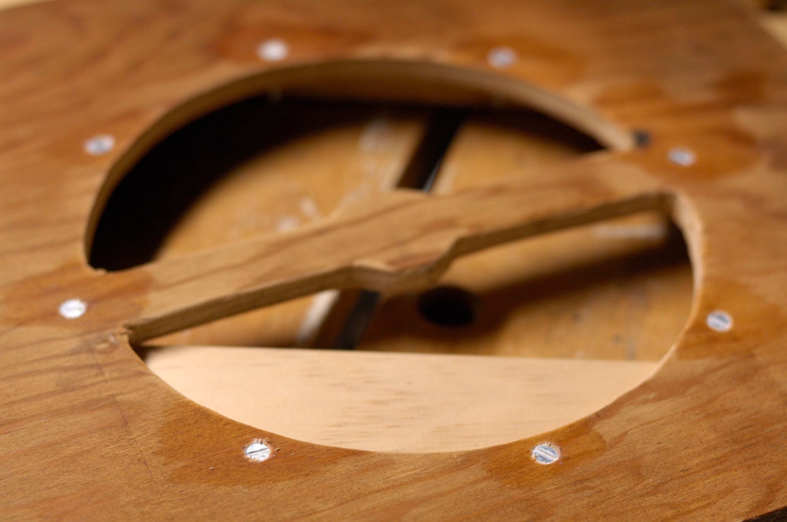
Front Face / Speaker Baffle
The front was cut from 3/8 in. plywood with a sabre saw. It was traced on a piece of butcher paper, in case the cabinet wasn't quite square. It wasn't traced directly, so that one edge could more accurately be aligned with the "factory edge" of the plywood. The front is large enough to accommodate a 10 in. speaker, if desired.
A small "beam blocker" circle was left in the center, to block the harsh treble that usually projects at a narrow angle straight from the speaker.
Eight holes were drilled and countersunk for the mounting screws. The screws fit very snugly, but were also PVA glued in place.
Grill Cloth
The grill cloth is undyed burlap; a nice open weave that's very transparent to sound waves.
It was simply wrapped over the front and stapled in the back, carefully. It's easy to keep it tight and straight. No glue was used.
Attaching the Baffle Panel
A bottom cleat, made from a section of 1x2, was added to the cabinet.
The front baffle panel was screwed to the cleat at the bottom, and to the chassis supports at the top. Finishing washer dress up the screws.
Step 19: Links

The Valve Wizard
GREAT stuff, especially the "Triode Gain Stage" PDF.
http://www.freewebs.com/valvewizard/index.html
Tales From The Tone Lounge-- Mods and Odds!
Really good practical info on modding preamp sections.
http://tone-lizard.com/Mods_and_Odds.htm
The Definitive database of tube datasheets
http://tubes.mkdw.net/index.html
Parts
Ebay.com, of course, is a good source.
Step 20: OH, Man...I Wish I Had...

No project is without lessons learned. In this case, I wish I had:
--Used a heaver, possibly stock, metal chassis.
--Substituted a 10 inch speaker.
--Used a turret board, instead of point-to-point. The more I modified the project, the more a tangled web it became. After this project, layout for turret board makes perfect sense--tubes on the back, controls on the front and the component board between....
So, additionally, the chassis layout sucks, too. Initially my main concern was to keep the preamp tube far away from the power transformer. But the lead-dress is awful. The "star-ground" is in the wrong place, too.
It must be said: despite the "rat's nest," the amp is quiet.
--The filament tap is not separated from the HV secondary. Too bad I didn't just use a separate 3A 6.3v transformer for the filaments, and added the 6-7V from the main transformer to the HV tap (about 149V, vs 142V.) After all, I had to add the wallwart for the preamp anyway....
--Used tube sockets with some sort of retaining clips--the chassis is upside-down. It hasn't been a problem yet, but eventually... All new ceramic sockets might be better, too.
Oh, and I did add a negative feedback loop. Although it did lessen the punch and (audio) feedback, and tone down the bass, it added a bit of "fartyness," too. That flabby, farty tone was present whether the nfb was switched in or not.
So I ripped it out right away.
Sometimes this is just a solder-joint issue, sometimes it's a bad cap. But it might be a routing problem, which at this point is beyond fixing without a complete rebuild.
Step 21: Finding Parts for a Build (transformers, Etc.)


The "Iron"
If anyone replicates this build, it's unlikely they'll find a 142V transformer. So how to replace that part?
-- One solution is a 230V primary (euro mains), 300-0-300V secondary trannie. If you're in the US, connect the primary to standard US 117V mains, and you've got a 150-0-150V secondary--perfect! However, any filament taps will be halved, so a separate 6V transformer is needed.
-- Try a "universal" isolation transformer--one that has 117 and 230 primaries, and a 117 secondary. Wire that backwards, and tap 230 volts. Then use a "choke input filter"; the choke is first inline after the rectifier, not a cap. that should drop the voltage to less than 210V (vs. 322V for a rectified 230 RMS.) No filament taps, so same as above...
-- Hammond makes an excellent power transformer:
263CX 116VA, sec. 180-0-180, DC ma 250, Fil. #1(rectifier) 5.0v @ 3a ct.
It's 180V, but with a tube rectifier like a 5U4 instead of the SS bridge, the output voltage should be very near 200V. It has a 5V source for the rectifier--a separate 6V filament transformer would be needed...
-- For the PS inductor, Any 4 to 10 Henry inductor will do, but should be rated for at least 120mA @ 250V. New, 4 to 10 Henry inductors are easy to find. The power supply could be redesigned with an initial RC filter, replacing the LC filter (that would be a cheaper option, too.) But that wouldn't be as efficient as the LC setup, and also change the load on the power transformer. Not only would the PT need to be large enough to handle it, it might necessitate changing the resistance values in the power supply also.
NOTE:
Under NO circumstances should an autotransformer be used in place of a standard power transformers. Autotransformers are often used in international voltage converters--i.e., to use U.S. appliances with European wall voltages.
Autotransformers are not isolated, and would constitute a serious hazard in guitar amps.
--A separate 6.3V, 3 amp transformer for the filaments (heaters) will be necessary unless you get lucky and find a trannie with secondaries of 150V and 6V. Again, large current draw for the heaters--2.7 amps @ 6.3V.
-- The Edcor OT is pretty much perfect. Used output transformers are trickier to find, however, due to the lower load resistance of these tubes. It's pretty easy to find OTs for 6V6's, 6L6's, etc., but not for the 50L6 family--except for low-wattage, single tube radios, etc. But that iron is usually less than 5 watts, and not useful for this build.
Tubes
-- Not an issue, NOS tubes are plentiful.
Step 22: The End???

More parallel 6DG6GT SE designs (or parallel PP) are churning away in my head. A three tube, 11 or 12 watt amp would be quite impressive. Or two parallel stages of two tubes each-- a "twin parallel" design.
And can the 6DG6GT be run higher than 200V, squeezing-out more wattage? The max spec for the 6V6 is 250V, yet they are commonly pushed to 350v, 400V and beyond. NOS tubes are notorious for absorbing punishment, and they keep on ticking...
So why is this class of tubes (6DG6GT, 50L6, etc.) ignored by amp builders today?
--They are a somewhat underpowered compared to classic power tubes (hence this "parallel" design.)
--They were commonly used in AC/DC "radio tube" amps, which many of today's builders don't respect.
--50 volts for the heaters is tough to achieve. In the old amps, all the tube were wired in series, and the wall "mains" were used directly. This is unacceptable, today. Actually, these tubes were originally designed to run the heaters directly off the mains...(although not the 6DG6DT variant.)
--Many modern builders aren't aware of the lower filament voltage variants (I, for instance, didn't know about the 6.3V version...)
Step 23: Update, V0.2

Here's the entire schematic (V0.2), with a few changes...
-- The whole schematic is now a single graphic.
-- One of the power amp cathode bypass resistors has been reduced from 50uf to 20uF. Even less capacitance is an option...
The Screen Supply Switch
An additional source for the 6DG6GT screens has been added: the Edcor output transformer has a 40% screen tap. Now this is switchable, between the old PS B.3 tap, and the transformer tap.
A bit of research confirms that a pentode screen operating from a OT tap is running in ultra-linear mode. Although I see no evidence to support the claim "...a maximum power output equal or even greater than the strict pentode operation of the tube..."
In fact, it's definitely a softer, mellower, "woodier" sound (with some volume attenuation.) By alternating between the old and new schemes, the switch acts, in a way, like a simple boost.
Of course, using the screen tap on the OT shifts the current draw for the screens from B.3 to B.1....more current draw on B.1 reduces the voltage available on the B.2 for the preamp. This may also explain the volume drop.
Alternative Power Supply
The PDF below includes an alternative power supply which uses off-the-shelf (Hammond) transformers in place of my own "scrounged" inductors. It utilizes a tube rectifier instead of the SS bridge--which is why the higher voltage (180V) PT works.
I haven't built it, so a little experimentation is called for....(in fact, read the pdf carefully, some modifications are suggested.)
External Cab
I've been using the amp a lot lately with a 2x12 cab. There's a lot more headroom with the larger speakers / cabinet combination.
It's definitely bassier and louder, too. I still switch to the internal speaker when I want to drive the amp to the edge of instability (feedback, etc.), but it's a more vintage sound with the cab.
Step 24: Update, V0.3


Sept, 2008
I continue to refine the amp. It's been several months since the initial build, and it's still going strong. Any concerns I had-- for instance the power tube cathode bias being too "hot"-- are gone... Here are the next round of changes (see the new schematic):
(***there's another change I won't be adding to the schematic yet...we'll see if I like it first..***)
1) Added a screen-grid stopper resistor to the ultra-linear tap of the output transformer. It's there to prevent too much current from frying the screen.
It's added only in series with the tap, not with the main screen supply. The main supply already has the current dropping resistors in the power supply.
If anything, it's addition has brightened and added gain to that option of the screen supply (there are two options available.)
2) Removed the extra cathode bypass cap on the second power tube. It just didn't make a large difference.
It's still not a bad idea--only have a double pole switch add / remove capacitance from both 6DG6GT's at the same time. That would make a noticeable difference. Maybe start with two 10uF, and switch in another pair of 30uF caps....
3) Added an external speaker jack. I've been experimenting with two cabs.
-- a 2X12 cab with two old CTS organ speakers (with the "whizzer cones.") It's an old bass cab.
-- a 4x12 cab with two Eminence speakers (and the other two holes empty.)
It's pretty freaking amazing how loud this amp is with a 2x12 cab. I literally can't hear myself shouting...
Of the two cabs, the Eminence speakers have a harder, more aggressive sound. Which you would expect. What I didn't expect is how much I like the old CTS speakers--especially when the amp isn't cranked. It's hard to describe--but a very full, vintage sound that loves single-coil pickups....
Step 25: Local NFB Option, V0.4


Late Sept., 2008
While reading about the weird additions to the Fender Bassman (Ver AB165), I noticed a comment about a local Negative FeedBack loop on one of the gain stages. In theory, this should add some compression to the amp. NFB will also extend the frequency response of the amp.
NOTE: Just so we're clear:
Negative Feedback results in less of the high frequency feedback squeal usually associated with guitar amps (that's "positive feedback.") Negative is good, in this case.
So I tried it on the second preamp stage. I really like it! Of course, a NFB (negative feedback) loop will subtract a bit of gain from the amp--hence it's "optional" nature.
For a bit of a twist, I ran the feedback signal back through the tone stack. Note that the "presence" control still works with the NFB, but has less effect on the sound.
Any value from 100K to 680K will probably yield results...pick one that suits you. Rule-of-thumb:the lower the resistance in the loop, the more feedback and the more signal loss. So lower values like100K will have more effect on the tone, but make the amp quieter and less overdriven. it's certain possible to have a switching option, also.
NOTE:I did add a switch for the NFB loop, and it works great. Switched in, the sound is definitely sweet and lush. Switched out, the punchy, raw sound returns.
The cab back photo shows the switch, along side the screen supply switch. The switch has now been reassigned for different uses--twice. Maybe a relay / footpedal setup in the future?
Participated in the
The Instructables Book Contest


