

Introduction: Guy-Manuel Daft Punk Helmet With Programmable LED Lighting


In this Instructable, you will be building a Guy-Manuel de Homem-Christo Daft Punk Helmet with programmable LED lighting. It's a long project that will take several tens of hours of work. Areas of expertise which will help with this build include: 3D printing, prop work, laser cutting, soldering, circuit board building and Arduino coding, although descriptions will be full and detailed so please don't feel discouraged if you have experience in none of these fields.
The Helmet itself is comprised of a 3D printed chassis, vacuum formed visor and LED lighting system controlled by an Arudino Uno. I originally build the helmet in 2013 to take to Glastonbury Festival and provided files and instructions at that time on my Thingiverse and blog, however now I am rewriting the build in greater detail for Instructables.
If you like this Instructable, please vote for it in the Instructables 3D Printing Contest or click the "vote" button in the top right! Thanks :)
Step 1: Parts and Tools List
Required Parts
- 3D printed parts in white PLA
- 3D printed parts in natural PLA (translucent)
- A selection of M3 nuts and bolts
- Modelling clay
- Car body filler e.g. Isopon P38
- White surface primer spray paint
- Metallic gold spray paint
- Black spray paint
- Thick equipment wire in green, white and red (I purchased 5 m of 24/0.2 mm 18-19 AWG of each colour)
- Plenty of standard equipment wire (7/0.2 mm)
- 1 x Arudino Uno
- 5 mm LEDs
- 6 red
- 6 orange
- 6 yellow
- 6 green
- 6 blue
- 6 pink
- 6 x 2.2 kΩ resistors
- 3 x 330 Ω resistors
- 3 x 120 Ω resistors
- 6 x 2N2222 transistors
- small piece of stripboard (at least 20 x 9 holes)
- 1 x 8 AA battery holder
- 8 x AA batteries
- 1 x 2.1 mm male power plug
- 1 x 10kΩ potentiometer
- 1 x SPST switch
- 2 x 800 by 500 pieces of 6 mm thick MDF
- 1 x 300 mm long 6 mm diameter wooden dowel
- 1 x 0.5 mm A3 piece of PETG
- VHT Niteshades
- Self adhesive foam roll
- Cable wrap
Required tools
- Access to a 3D printer, or you can have all the parts printed for you using the "Print with 3D Hubs!" button.
- A hot melt glue gun and plenty of glue sticks
- Modelling clay
- Sand paper and sanding block
- Recommended: A power sander such as the Black & Decker Mouse Sander
- Safety goggles
- Dust mask
- Electric drill
- A soldering iron and solder
- USB type-A to USB type-B cable
- Access to a laser cutter OR a CNC wood router
- Access to a vacuum former
- Craft knife or sharp scissors
Step 2: 3D Printed Part Files
Some parts will require rotation and/or support material. You will require the following parts in white PLA:
- 1 x Case
- 1 x CaseLid
- 1 x HelmetBack
- 1 x HelmetFront
- 1 x HelmetLeftBottom
- 1 x HelmetLeftTop
- 1 x HelmetRightBottom
- 1 x HelmetRightTop
- 1 x HelmetTop
- 1 x HelmetWirePlate
- 12 x LEDBank
You will also require the following parts in natural (translucent) PLA:
- 1 x LEDDiffuserLeft
- 1 x LEDDiffuserRight
The Helmet and Diffuser parts may need scaling if your head is significantly larger or smaller than mine. For comparison, the circumference of my head is 55 cm.
Attachments


Step 3: Joining the Helmet


Once you have all the 3D printed helmet parts, you will need to join them together to form the complete helmet. Using M3 nuts and bolts and a generous amount of hot melt glue, join:
- HelmetBack
- HelmetFront
- HelmetLeftBottom
- HelmetLeftTop
- HelmetRightBottom
- HelmetRightTop
- HelmetTop
Now would be a good time to check that the helmet fits over your head well. Ensure that there is plenty of space!
Step 4: Crack Filling


The smoother the finish of the helmet before it's painted, the better it will look. The first step to achieving this smoothness is to fill in any cracks or blemishes post-print. Push modelling clay into all gaps, and sand with sand paper or your power sander until smooth.
Step 5: Surface Finishing


Prior to painting the helmet, you will need to ensure a super smooth surface finish so that when painted it shines like the real thing. Coat the helmet with car body filler, and wait for it to dry.
You may want to avoid detail sections such as below the earpieces if you don't want to spend a long time sanding intricate holes with a needle file or rotary tool.
You'll then need to sand the helmet a lot. It's recommenced that you use a power sander to speed up this sanding. Start with a coarse grit and gradually move towards finer grit sand papers to get maximum smoothness.
Be sure to do this work in a well ventilated area and wear safety goggles and a dust mask for your own protection.
Step 6: Painting


You should first spray paint the helmet with a few coats of white surface primer, before applying the metallic gold. Be sure to leave plenty of time for the paint to properly dry, and do spray paint in a well ventilated area.
If you don't have experience spray painting, I recommend doing a little research on the internet to learn proper spray painting technique - it will make a lot of difference to the final appearance of your helmet.
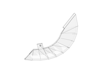
Step 7: Helmet Wire-plate


The final part of the basic helmet is the back wire-plate.
To build this, first take the 3D printed HelmetWirePlate part and liberally apply black spray paint (again, in a well ventilated area).
Next, take your thick equipment wire and attach it in strips to the wire-plate using hot melt glue. The finished wire-plate should pop neatly inside the helmet, and should be secured with additional hot melt glue.
Step 8: Electronics


Next, you will need to build the electronics which interface between the Arduino Uno and the LED lights. Included is a circuit diagram of the completed helmet and control box.
You will use the Digital pins 3, 5, 6, 9, 10 and 11, since these pins are able to be used in PWM mode which lets you dim the LEDs, rather than simply switch them on and off. Each pin is attached to a 2.2k Ω resistor and then the base pin of a 2N2222 transistor. When an Arduino pin is switched on, it opens the transistor it is attached to, and power flows from the battery pack, through the LEDs, through a resistor, through the transistor (from the collector to the emitter) and back to ground.
Note that the 330 and 120 Ω resistors were chosen based upon the maximum currents of the LEDs I purchased. You may want to check what resistors are required for your LEDs using an online LED calculator such as the one at led.linear1.org/led.wiz.
The second two diagrams show how to mount the resistors and transistors to your stripboard which will connect from the Arduino Uno to the LEDs in your helmet. Note the orientation of the 2N222 transistors, since they will not work if they are the other way around. Also note the Xs - here you should use an electric drill and small drill bit to gently remove the tracks on the underside of the stripboard, so that current cannot flow across this area of the board.
Once you have properly connected all of the components shown on the circuit diagram, you can assemble them inside the 3D printed case using the parts Case and CaseLid, and some M3 nuts and bolts.
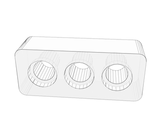
Step 9: LED Lighting


In this step, you will attach the LED lighting to your helmet.
First, take your 12 3D printed LEDBank parts, and embed three LEDs of the same colour into each. Join the legs of each triplet of LEDs so that they are connected in series (be sure to get them the right way round - polarity is important for LEDs).
Solder some long leads onto the ends of each triplet, and join the positive and negative leads of each same-coloured triplet so that they are wired up in parallel.
It's then time to use your hot-melt glue gun to attach each LEDBank onto the 3D printed LEDDiffuserLeft and LEDDiffuserRight parts. The LEDDiffuserLeft and LEDDiffuserRight parts should then be attached to the helmet using hot melt glue.
All of the positive leads can be joined together to a main power supply lead, which should be long enough to reach the control box (1 - 2 m). The negative leads of each pair of same-coloured triplets should each have a long wire (again, 1 - 2 m long) and should be wired to the appropriate points on your stripboard (refer to the earlier diagrams).
Now would be a good time to upload the control code to the Arduino and test the electronics. First, you will need to download the Arduino software from the Arduino website. Then, with the 8 AA battery pack unattached, connect your Arduino Uno to your computer using a USB type-A to USB type-B cable. Open the Arduino software, open the attached FullControl.ino, and upload the code to your Arduino. The lights should begin to animate - check that the potentiometer can be turned to adjust the animation speed and that the on/off switch can be used to enable and disable the lighting. Next, unplug the Arduino from your computer and power it using the 8 AA battery pack, and perform the same checks. If it's all working, you're good to go. If not, check your wiring and refer to the earlier diagrams.
Feel free to modify the code to add, remove or change animations (or re-write the code entirely!) for your helmet.
Using your hot-melt glue gun, organise the wires and glue them inside the earpieces and around to the back of the helmet so that they do not snag on your head when wearing the helmet.
Attachments

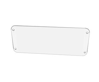
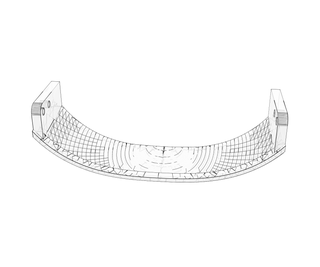
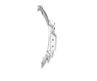
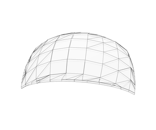
Step 10: Creating the Visor Mould


You will be making the visor for the helmet using a vacuum former, so you require a mould over which to stretch the PETG.
If you have access to a CNC wood router, you can create the mould directly from a block of wood. The attached VisorMould.stl can be used for this (please note that VisorMould.stl should not be 3D printed as it would likely not be appropriate for vacuum forming if manufactured in this way).
If you do not have access to a CNC wood router, you will be creating the mould the slow way, using a laser cutter.
You may be able to join a local hackspace or workshop to get access to a CNC wood router or laser cutter.
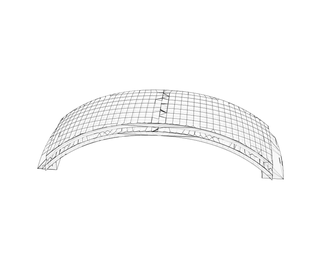
Using the two attached .dxf files and a laser cutter, cut the 19 mould slices out of 6 mm thick MDF. Check that they stack properly. Saw the 300 mm long 6 mm diameter wooden dowel into two roughly equal pieces and use them to align the slices.
Disassemble the mould and begin to rebuild it, this time generously applying wood glue between each layer. Once the entire mould has been assembled, apply weight and leave to dry.

Step 11: Sanding the Visor Mould


If you were able to create the mould using a CNC wood router, you can skip this step.
If not, you've got a lot of sanding on your hands. Without a power sander, this step could take a very long time.
You'll want to use the coarsest grit sand paper you can find for the majority of this step. Keep sanding until the ridges between each slice are no longer visible. Try to ensure that the mould retains a smooth curve all over (see pictures).
Once the ridges are no longer visible, use progressively finer grit sand papers to get a good surface finish.
Step 12: Vacuum Forming and Tinting the Visor


Next, it is time to vacuum form the PETG over the mould to form the visor. As with the spray painting, I recommend you do some research on best vacuum forming practices. If you don't have direct access to a vacuum former you may be able to join a local hackspace or workshop to gain access to one.
Once you have formed the visor, carefully cut it to out using a craft knife or sharp scissors. Leave plenty of space as you will need to trim the visor in the next step so that it fits the helmet correctly.
To tint the visor, you will use VHT Niteshades. Spray very thin coats across the inside of the visor from a reasonable distance - do not spray close to the visor or you will end up with a blotchy tint. Spray only in a well ventilated area. Use several coats, and allow the visor to dry between coatings.
After each coat, have a look through the inside of the visor from close up and stop when it's sufficiently dark - you want to be able to see out of your helmet!
Step 13: Attaching the Visor, and Finishing Touches


Attach the visor to the helmet using hot-melt glue - be aware that the visor will probably need some trimming to fit the helmet.
If you like, you can take a fine paintbrush and some black paint and paint over the hot melt glue to obscure the seam where the visor meets the helmet.
Finally, cut out some self-adhesive foam roll and attach it to the back of the wire-plate and the inside of the LED diffusers, to maximise comfort when wearing the helmet. The glue on the self-adhesive foam roll may not be strong enough, in which case use more hot-melt.
It's a good idea to strengthen anywhere where the cables might be bent around a lot with hot-melt glue, otherwise the wires may break.
You may also want to wrap the cable which connects the helmet with the control box with cable wrap to protect it.
Step 14: Complete


Congratulations on completing your Guy Manuel Daft Punk helmet! You are now the coolest robot in your neighborhood.
If you would like to make the pictured gloves, you can find the necessary files on my Thingiverse here.

Participated in the
3D Printing Contest


