

Introduction: Halley: Ambassador Robot 001


Here is a quick description:
A 2.6 foot remote-operated humanoid robot designed to be capable of emulating human communication.
Here is a longer description:
Ambassador Robot No. 001, also known as Halley, is a 2.6-foot humanoid automaton built for the sole purpose of exploring what it means to be human from a non-human perspective. The primary means of achieving this is through human-robot interaction, where the robot, Halley, emulates as many human functions as possible while interfacing with another person. In order to connect with the idea of being human, a humanoid shape of respectable size is deemed necessary, along with an array of face-to-face communication techniques. A speaker, camera, and microphone satisfies the need for basic sensory input and output. Gestures, such as raising hands to ask questions, are supported by Halley's movable arms and legs. Finally, and perhaps most importantly, the ability to express emotions will be achieved through the clever use of an Android phone as a face. The ultimate goal for this project is to have Halley take the place of a student in a classroom.
Notes:
This is a very advanced project and assumes knowledge of laser cutting, 3D printing, usage of a machine shop, soldering electronics, and a variety of other things. The expected time to finish this project is a couple months working on and off, and a couple weeks working full time. The expected cost for this project is roughly 500-800 USD. I would not advise beginners to do this project!
Step 1: Parts You Will Need:


(Images above are a small sample of the parts you will need for this project.)
Specific Parts:
- Arduino Mega 2560 (https://www.sparkfun.com/products/11061)
- 3-foot USB A to B Cable (http://www.amazon.com/Belkin-3FT-USB-Device-Cable/dp/B00004Z5IU)
- Samsung Galaxy Light SGH-T399 (http://www.samsung.com/us/mobile/cell-phones/SGH-T399DNATMB)
- AUVIO Universal Portable Speaker 4000372 (http://www.radioshack.com/auvio-universal-portable-speaker/4000372.html#.VP8e1_nF-So)
- 3-foot Audio Extension Cable (http://www.amazon.com/C2G-Cables-40408-Female-Extension/dp/B0012MMW7E)
- 21x Power HD-1201MG servomotors (http://www.hobbyking.com/hobbyking/store/)
- 10x servo extension wires (http://www.amazon.com/300mm-Servo-Extension-Futaba-10pcs/dp/B00HCFI3SC/ref=sr_1_6?s=electronics&ie=UTF8&qid=1426006009&sr=1-6&keywords=10x+servo+extension)
- Plugable USB 2.0 7-Port w/ 3A Adapter (http://www.amazon.com/Plugable-Terminus-Technology-backwards-compatibility/dp/B003Z4G3I6/ref=sr_1_14?s=electronics&ie=UTF8&qid=1426006055&sr=1-14&keywords=plugable+usb+3.0+7port)
- 5V 10A switching power supply (http://www.adafruit.com/product/658)
- Barrel Jack adapter 5.5x2.1mm (https://www.sparkfun.com/products/10288)
- large perfboard (http://www.allelectronics.com/make-a-store/item/pc-3/solderable-perf-board/1.html)
- 3x 1/8 12x24 Acrylic Sheet (http://www.mcmaster.com/#acrylic/=w90lub)
- 1x 1/8 12x12 Acrylic Sheet (http://www.mcmaster.com/#acrylic/=w90lub)
Common Parts:
- Solder
- Superglue
- 3D Printer filament
- Velcro Hook and Loop Tape
- lots of assorted wires
- assorted Molex pins/connectors
- assorted breakaway headers
- S/S FHSCS 2-56x3/8 screws
- S/S FHSCS 2-56x1/2 screws
- S/S MS NUT 2-56 nuts
- S/S/ F/W .093x.250 washers
- S/S FHSCS 4-40x1/2 screws
- S/S FHSCS 4-40x5/8 screws
- 4-40 MS NUT S/S nuts
- F/4 S/S .125x.280 washers
- 6-32 5/8 SHCS S/S screw
- 6-32 Nylok Nut S/S nut
- F/W S/S .156x.312 washers
Step 2: Tools You Will Need:


(Images above are a small sample of the tools you will need for this project.)
Hardware tools:
- 3D Printer
- Laser Cutter
- Shop Drill
- Hand Drill
- File
- Soldering Tool
- Solder Helping Hands
- Solder Sucker
- Solder Fan
- Goggles
- Wire stripper/clipper
- Crimper tool
- Assorted screwdrivers
- Assorted hex keys
Software tools:
- Rhino3D (https://www.rhino3d.com/)
- Arduino (http://www.arduino.cc/)
- Unity3D (http://unity3d.com/)
- Android SDK (http://developer.android.com/sdk/index.html)
Step 3: Overview:


(Images above are rendered images of the robot you will be building.)
Before we begin, I would like to go over a brief overview of the steps required to build this robot.
HARDWARE
- 3D Printing.
- Laser Cutting.
- Assembling the Head.
- Assembling the Arms.
- Assembling the Legs.
- Assembling the Torso.
- Attaching the parts together.
- Assembling the Backpack.
- Creating the Electronics.
- Attaching the Backpack.
SOFTWARE
- Arduino
- Unity3D
- Android Phone Face.
I have provided all the necessary files to build this robot in this GitHub repository: https://github.com/johnchoi313/Halley-Ambassador-Robot-001
You will reference and use the files in this repository throughout the building of this project. For all assembly steps, it will be extremely helpful to look at the actual CAD model to see exactly how the parts are going to mesh. The Rhino CAD file should be located in the CAD folder, labeled "Halley Render.3dm", or here in the GitHub repository: https://github.com/johnchoi313/Halley-Ambassador-Robot-001/tree/master/Halley%20CAD
Note that if you do not have Rhino3D, or prefer to use another CAD application such as Solidworks, I have provided files named "Halley_Robot" in OBJ, STL and STP formats, which can be imported directly to most 3D softwares. They are located in the same folder.
Step 4: 3D Printing


Use a 3D printer to create the hands, feet, torso supports and backpack connector.
If you have a MakerBot printer, print the following .thing files, located in the Halley CAD folder.
- foot.thing (2x)
- left_hand.thing
- right_hand.thing
- body_support.thing
- Backpack_velcro.thing
If you are using some other 3D printer, import the following files and print them. They are located in the same folder.
- foot.stl (2x)
- left_hand.stl
- right_hand.stl
- body_support.stl
- Backpack_velcro.stl
Note: If you do not know how to use a 3D printer, I recommend looking up the documentation for the specific model you are using. As I stated earlier, this project is very advanced and assumes knowledge in a lot of things, including 3D printing.
Step 5: Laser Cutting Acrylic


You should have 4 sheets of 1/8 inch acrylic for this step, of which three are 12x24 and one is 12x12 (in inches).
Laser cut these templates, located in the Halley CAD folder:
- Halley_black.dxf (12x24)
- Halley_clear.dxf (12x24)
- Halley_white.dxf (12x24)
- Halley_head.dxf (12x12)
Although the colors you use do not matter, I recommend using 3 different colors, where Halley_head and Halley_white have the same colors. You can also look at the main CAD render to get an idea of how the colors will mesh together.
Optionally, you can also engrave patterns on the laser cut pieces for that extra design aesthetic. Just in case you wanted to engrave the same patterns as I did on mine, you can import the following raster images in your laser engraving software:
- HalleyName.png
- roboclub.png
- FRFAF.png
- author.png
- usflag.png
Step 6: Assemble the Head.


Now that we have the parts we will need, we can now begin assembly. The head is a good starting point, since it houses a good variety of electronics. Once you understand how to assemble one part, assembling the rest should be relatively straightforward. Because of this, I will describe assembly of the head in great detail while being less detailed for the other parts. Again, I highly recommend you look at the actual CAD model in Rhino while assembling the robot, located in the Halley CAD folder.
Begin by collecting the necessary pieces for the head, which include:
- 1x servomotors
- AUVIO Speaker
- Phone (this will be detachable)
- All the associated acrylic pieces.
- Assorted screws, washers and nuts.
I would start by building the lower "jaw" of the robot, where the speaker is housed. Insert batteries into the speaker, and make sure it works. Use the size 40 screws to fasten pieces together, along with the respective nuts and washers. Note that the speaker wire should dangle outside of the hole on the acrylic piece that holds it in place, and there is a hole for the button on the side acrylic. Fasten this to the front face plate.
Now build the neck of the robot. This should have 1 servomotor for pitch. Use the large size 36 screws and the Nylok nut for the actual joint. Fasten this to the lower plate on the head. After you have completed this step, connect the rest of the head together. At this point, you should be able to insert the Android phone into the head (the head is designed so that you can easily insert and remove the phone).
General Assembly Tips (for all parts):
- Depending on where you ordered the acrylic and how it was laser cut, it may be too tight or too loose. If it's too tight, rake off the side of the acrylic until it fits snug. If it's too loose, tightening the screws should take care of most of it. (Although I don't advise this with parts that need to be frequently removed or moved, a small amount of superglue can also help tighten loose areas.)
- Be careful when handling acrylic! Due to its physical properties, acrylic tends to shatter upon impact, so a drop from 3 feet on concrete might render the acrylic piece unusable.
- Carefully consider the order in which you are going to add the screws. Because of the shape of certain parts, doing some parts first might make it harder to do other parts later.
- Most servos come with servo attachments, which are used to mount to other pieces. The screws will not fit on the servo horns or the acrylic pieces that connects to the servo horn, so use a shop drill or a hand drill to make those holes larger.
- Before attaching servos, make sure they are oriented correctly. This can be done by attaching servos at their max/min positions on their respective joints.
- Although this project was planned very carefully, you are almost guaranteed to have "unforeseen difficulties." Because of this, it is a good idea to have a variety of shop tools along with the 3D printer in case you need to improvise.
Step 7: Assemble the Arms.


In the same fashion as the head, you will now assemble 2 arms.
Begin by collecting the necessary parts for the arm, which include: (per arm)
- 4x servomotors.
- 3D printed hand.
- Associated acrylic pieces.
- Assorted screws, washers and nuts.
There are three main sub-parts to consider per arm: the lower arm, the upper arm, and the shoulder. Attach the servo horns to their respective acrylic pieces (a drill may be needed to make the screws fit). Assemble the lower arm and the upper arm (2x servomotors) and connect them with the associated screws. Then assemble the shoulder (2x servos). Connect the shoulder to the rest of the arm. You should now have a 4 degree-of-freedom arm. Note that because the hand is 3D printed and is fixed; it will not be able to grab things and is purely aesthetic.
Assemble the other arm in the exact same way. (Because the 3D printed hands are mirrored, make sure you have the hands on the correct arms!)
Step 8: Assemble the Legs.


In the same fashion as the arms, you will now assemble 2 legs.
Begin by collecting the necessary parts for the leg, which include: (per leg)
- 4x servomotors.
- 3D printed foot.
- Associated acrylic pieces.
- Assorted screws, washers and nuts.
There are 2 main sub-parts per leg: the lower leg and the upper leg. Again, begin by attaching the servo horns to their respective acrylic pieces. Assemble the lower leg with the 3D printed foot (2x servos). Then assemble the upper leg (2x servos). Attach the lower leg to the upper leg. Take care to make sure the servos are properly oriented before attaching the joints together. Note that because the robot is made out of acrylic and the fact that the servos are not strong enough, the robot is very unlikely to be able to walk.
Step 9: Assemble the Torso.


Now that we have completed the appendages, we can now build the center of the robot: the torso.
As usual, begin by collecting the necessary parts, which are:
- 3D Printed Body support
- Associated acrylic pieces.
- Assorted screws, washers, and nuts.
We will be building the lower torso during this step, as the upper torso will be done while attaching the arms. Fasten the 3 servomotors onto the torso acrylic pieces. The single servo on the front is for upper chest movement, and the other two servos on the bottom are for attaching the legs. Attach the 3D printed body supports in the middle of the lower torso as shown in the diagram, and fasten them with screws (some holes will need to be drilled). Finish the rest of the lower torso as shown in the CAD model.
After this step, we will be attaching the various body parts together to form the humanoid robot.
Step 10: Attaching the Body Parts Together.


At this point, much of the work assembling the body has been completed, and we may now start attaching the various parts together. There are 3 phases of attachment we must consider, which are attaching the legs, attaching the arms, and finally attaching the head.
Attaching the Legs:
We begin by attaching the legs to the torso. Note that you will have to assemble the intermediary part between the torso and the leg before making the attachment. It will probably be easier to attach the leg while the robot is laying down on your work space. At this point, you should also attach the upper chest pieces to the lower torso.
Attaching the Arms:
Just like you attached the legs to the torso, now attach the arms. Again, they will probably be easier to attach while the robot is laying down.
Attaching the Head:
Finally, attach the head to the upper chest torso.
After the completion of this step, you should have a robot that looks truly humanoid.
Step 11: Assembling the Backpack.


The final piece is the backpack. The backpack houses all of the necessary electronics and control mechanics for interfacing with the robot. It is also where the main power is routed.
Begin by collecting the necessary pieces:
- 7 port USB hub
- Associated acrylic pieces.
- Assorted screws, washers and nuts.
There are 3 layers to consider with the backpack: the front, the middle and the back. Start with the back and work your way upwards from there. The USB hub should fit tightly between the back and the middle plates. The Arduino Mega and the perf board will sit on the middle plate so that the electronics are clearly visible through the top plate.
Although the USB hub is optional, it allows for powering additional electronics mounted on the robot, such as webcams or Raspberry Pis if you choose to expand upon this project.
Step 12: Creating the Electronics.


The idea of the electronics is simple - what we need to do is hookup 21 servomotors to the Arduino Mega.
If you've had any experience with RC servomotors, you'll know there are 3 pins for each servo: red/orange for voltage input, black/brown for ground, and white/yellow for signal. Because 21 servomotors will drive a lot of current, we will need a separate power source (in this case the 5V 10A Adapter from Adafruit). Thus, we will need to connect 5V from the adapter to every servo's voltage input pin, connect every servo's ground pin to the adapter's ground, and also hookup every servo signal pin to the Arduino Mega. Note that the servos should be wired in parallel, and the Arduino Mega grounded to the adapter.
There are many ways to solder the described electronics onto the perf board. I have provided a schematic for the wiring I ended up using. Since we are dealing with a large number of wires, I would advise soldering one step at a time. First, solder the breakaway headers onto the board. Then solder the white wires. And then the black wires. And finally the red wires. You can check that you did the soldering correctly by using a multimeter on various areas, one spot at a time.
When have completed soldering the necessary components onto the perf board, we can screw both the perf board and the Arduino Mega onto the middle plate of the backpack. The power from the 5V 10A adapter is routed through the 5.5x2.1 barrel jack adapter through heavy gauge wire to an optional power switch back to the perf board.
To actually connect the signal pins from the perf board to the Arduino Mega, I used crimped rainbow cables, although regular solid core wires should work fine as well.
Additional Tips while creating the electronics:
- Always use a fan to blow the fumes away. It is not advised to breathe the fumes that come from soldering.
- Be careful to make sure you do not accidentally "bleed" solder onto unintentional areas! This will make certain portions of the electronics useless at best and it will cause a short circuit at worst.
- If you do happen to make a mistake, use a solder sucker or an equivalent solder removal device.
- If you choose to do a different wiring from my schematic, plan out exactly how you plan to solder the components beforehand. You'll save countless hours of needless confusion and space on the perf board.
- If you wish, you can make a printed circuit board and order it online instead. If you choose to do this, you will have to design the PCB yourself.
Step 13: Attaching the Backpack.


This is the final step in completing the necessary hardware for this project. In other words, you will have a fully functional 2.6-ft humanoid robot after attaching the backpack (minus the software).
Begin by collecting the necessary parts:
- 3D Printed backpack connector
- Hook and Loop Velcro
- Superglue.
Superglue the 3D printed backpack connector onto the back plate of the chest. When glue has dried, attach strips of fuzzy loop Velcro onto the top of the connector, and attach equally-sized strips of hook Velcro on the back plate of the backpack. Now attach the backpack onto the back chest plate of the robot via the Velcro on the 3D printed connector.
Congratulations! You now have a fully functional and ready to use humanoid robot for use in animatronic animation research. Feel free to pat yourself on the back. The next steps will be setting up the software to control this robot, which you are free to use and expand upon. (You can also develop your own system to control this robot if you wish.)
Step 14: Arduino.
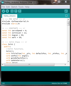
If you wish to use the software setup I have provided, you will first need to upload the Arduino code onto the Arduino Mega.
Open the Halley_Arduino.ino file located in the Halley_Arduino folder. Plug your Arduino onto your computer with your USB A to B cable. Go to Tools and change Board to Arduino Mega 2560 or Mega ADK. Go to Tools and change Serial Port to the name of the Arduino (on Windows, this is usually COM #, and on OSX, this is usually /dev/tty.usbmodem#). Now upload the code by pressing the Arrow shaped button on the upper left corner of the Arduino IDE window. Your Arduino's LED will blink a couple times while uploading the code, and the IDE will state "Done uploading" if the sketch has been successfully uploaded onto the Arduino Mega.
Basically what this code does is that the Arduino will continually wait for incoming strings in the format "Pos1:Pos2:Pos3:Pos4:Pos5:Pos6:Pos7:Pos8:Pos9:Pos10:Pos11", where every Pos corresponds to a servo along with its position as an integer ranging from 0 to 180. Once the Arduino parses the data, it will update every servo's position if it changed. Note that there are only 11 servos being controlled because code to control for the legs has not been written yet.
Step 15: Graphical Visualizer With Unity3D.

This is the Graphical Visualizer created with Unity3D to display a real time simulation of the robot while sending serial data to the Arduino for every servo position on the upper half of the robot. Although Unity is designed to make video games, it serves our purpose very well as a robot controller. Note that you do not need the Pro version for this project - the Free version should work just fine.
To begin, fire up Unity and open the project folder labeled "Halley Robot". This can be done by going to File->Open project and selecting the folder "Halley Robot". Then open up the scene titled "Halley_Robot". This can be done by going to the project pane and clicking on the Unity icon titled "Halley_Robot". Now, select the object labeled "Arduino Joint Control". In the Inspector, you should a plethora of settings. Change the one that says "Port" to the name of your Arduino serial port (on Windows, only ports ranging from COM1 to COM9 seem to work. On OSX, use the full name of the port, which is something like "/dev/tty.usbmodem#"). At this point, you should be able to press the Play button (shaped like a triangle on the upper middle part of the Unity window) to begin the running the simulation. If you do not see any glaring red errors, you should be able to fully control the robot at this point. Note that you will need your Arduino connected to run this program.
Here are controls I have set up:
- Press M to toggle mouse tracking. If enabled, the robot's head will follow the position of the mouse.
- Press any number from 0 to 5 on the Numpad on the right of your keyboard to control the arm positions. You can add more positions by modifying the "Pose Control" object in the hierarchy.
- Type in the text box in the upper left corner of the simulation window and press Speak to make the robot talk. This is actually powered by Google Translate for the text-to-speech function, so you will need an internet connection for this to work.
- Press any number from 0 to 6 on the upper portion of your keyboard to control the face. We will cover how to setup the Android phone to reflect the face in the simulation in the next step.
Note: If you are unfamiliar with how to use Unity, I recommend learning the basics here: http://unity3d.com/learn/tutorials/projects/roll-a-ball. While this explains the basics on how to use Unity, it really only scratches the surface on what Unity is capable of. If you are interested in learning more about Unity (or anything else for that matter), I would highly recommend spending a lot of time developing small projects on your own and gradually accumulating knowledge as you go along.
Step 16: Android Phone Face.


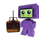
(Images above are just some of the faces the Android phone is capable of expressing.)
Although this part is optional, getting the Android phone face to be controlled in real time with the Graphical Visualizer will add a finishing magical touch to the robot. Note that this step is also expected to be the trickiest part of the software to setup correctly.
Follow the steps outlined in the link below to install Android SDK for your machine and get it working with Unity: http://docs.unity3d.com/Manual/android-sdksetup.ht...
Once the above step has been completed, you should be able to create Android Apps with the free version of Unity. Now, open up Unity and load the scene named "AndroidOSC". This is the scene that will be loaded as an Android app on your phone. Select the game object labeled "AndroidOSC" in the hierarchy. In the Inspector pane, change the Remote IP setting to the IP address of your computer. Then go to File->Build Settings, and click on the "Add Current" button on the window that pops up. Then click on "Player Settings" and change the Default Orientation to Landscape Right in the Inspector pane. Then, go to "Other Settings" and change the Api Compatibility level to .NET 2.0.
Finally, build the project by going to File->Build & Run (make sure you have your phone plugged in to your computer during this step). After your project builds successfully, you should be able to see two glowing blue eyes on your Android phone. Now, on your phone, go to Settings and enable WiFi. Note the IP address of your phone. Now, back in Unity, load the scene titled "Halley_Robot". Select the "HalleyOSC" game object and change the Remote IP setting in the Inspector pane to your Android phone's IP address. Run the Graphical Visualizer again by clicking the the triangle shaped icon in the upper middle screen. You should now be able to control the face of the Android phone by pressing the numbers on the upper portion of your keyboard.
Step 17: Conclusion


Congratulations! You have now successfully built a 2.6-ft humanoid robot for use in animation research.
The current iteration of this robot was used as an experimental telepresent robotic student that can take the place of real students in a university lecture setting. So far, it seems to work very well (and it also seems to possess an extraordinary capacity for livening up any dull lecture, both for professors and students).
My current software and design is highly limited in its capabilities; it's certainly not perfect as it is now and it probably never will be. But this is ultimately a good thing - this leaves plenty of room to improve, make modifications, and develop advancements in the field of robotics with research you may truly call your own.
If you choose to further develop this project, please let me know! I would absolutely love to see what you can make out of this project. If you have any other questions, concerns, or comments about this project or how I could improve, I would love to hear it.
In any case, I hope you enjoyed following this Instructable as much as I had writing it.
Cheers,
John Choi
Step 18: Credits

This project was supported in part by funding from the Carnegie Mellon University Frank-Ratchye Fund For Art @ the Frontier and was constructed at the Carnegie Mellon Robotics Club. Halley Ambassador Robot 001 was designed, assembled, coded and documented by me.
The Frank-Ratchye STUDIO for Creative Inquiry Official Site: http://studioforcreativeinquiry.org/
Carnegie Mellon Robotics Club Official Site: https://roboticsclub.org/
This project was heavily inspired by the Poppy Project: https://www.poppy-project.org/


