

Introduction: Build Your Own Aperture Science Portal Gun


Portal came to mind. Valve is a long-time favorite when it comes to awesome games for us, and so it then became a question of which Valve game to work from. Zoey from Left 4 Dead? Gordon Freeman of the fabled Half Life series? Or perhaps… could it be? Yes! Chell was our woman, and our own epic tale in the quest of a Chell costume began.
Of course, the first thing that any Chell costume needs is an Aperture Science Handheld Portal Device (or ASHPD), and in looking around on the internet, we couldn’t find that many tutorials (or even people who had actually done it in the first place). What we did find was severely lacking in either finesse, materials, or dedication. As we soon found out, if you weren’t willing to sink about $350 and four months of your waking life into the project, the end result wouldn’t be worth the sacrifice. Then we found the exception.
This instructable is going to start a little differently than most – with a word of thanks. Without his work and documentation (little though there is), none of this would have happened and we would have given up from not even knowing where to start. Harrison Krix of Volpin Props created the first real ASHPD, and his work also served as the basis for ours. His lack of real numerical documentation actually made the process much more fun and interesting as it forced us to rebuild his methods through guesswork and a little luck. It allowed us to create our own path, loosely based on his, that arrived at approximately the same place.
(We also didn’t have as much money to throw into it.)
We studied his pictures and made sketches as though studying for an upcoming test and slowly began our own journey into the world of Portal.
(Though first of all, we need a quick introduction! I, Joe, [the one writing at the moment] was responsible for the electronics, and my partner, Shelley, was responsible for the carving and for things requiring a steady hand, which I generally lack. For the rest of the gun, though, our efforts and skills were combined in such a way that we could probably refer to our creation as our nerd-child. And what a lovely nerd-child it is…!)
(Thanks to everyone who voted for us in the LED contest!! We managed to walk away with a Kindle, and for that we are incredibly pleased. Thank you again for showing your love!)
Step 1: Ingredients!


We bought and used a lot of things to make this project, and it was worth it all. Here's a more or less complete list:
Core:
4” diameter PVC pipe
3” diameter PVC pipe
2 4” PVC couplers
Lots o’ Cardstock (We managed to use about a 30”x24” sheet over the course of the gun)
About a gallon of Bondo + extra hardener (We blew through two quart containers and then gave up and bought a gallon. It’s still holding us)
Florists Foam (The largest we could find was about 3’x1’x4”, and it worked pretty well once we cut it in half and glued the halves together)
Superglue
Drywall Spackling
Gesso (a very bright white canvas primer)
Craploads of sandpaper, from grits 80-600. Trust us, you’ll need them.
Spraypaint: flat black, pure white, and clear coat gloss.
Plexiglass – amount unknown; we didn’t keep track because we had a near unlimited source.
Electrical Tape
1” glass lens
¼” black tubing
9 screws and nuts
20 gauge beading wire
dowel rod
Clear toilet plunger handle (preferably an adult sized one if you can find it – we used a child sized one ‘cause that’s all we could find, but there’s no room for error)
2 ½” diameter clear plastic tube
Packing foam
Painter’s tape
Plastic wrap
Electronics (Optional):
11 blue LEDs
11 orange LEDs
3 red LEDs
4.5v power supply (3 AA’s)
25 68 ohm ¼w resistors
about 6 feet of CAT5 cable
2 switches
some method of prototyping
Required:
Optimism
Patience
Steady hands
A willingness to get your hands dirty
Working knowledge of various power tools
A large work space (in our case, a living room, kitchen, and front yard gave their lives for this project)
Step 2: Gotta Have Tools!
Feasibly, this can be made with few tools, but at the very least you must have a Dremel. This tool has been our saving grace and go-to weapon for carving, shaping, cutting, smoothing, edging, and pretty much everything else. Ours is actually over a decade old, but still met our needs wonderfully! What we actually ended up using:
Dremel
Band saw
Scroll saw (jigsaw)
Belt sander
Spindle sander
Drill press
Most of these tools were only used once or twice during construction -- the ones we actually really ended up using were the Dremel, the drill press, and the scroll saw. The band saw was used to cut the PVC for the core, the spindle sander was used to clean the inside of the PVC after it was cut, and the belt sander was used to finish the barrel and do random cleanup every now and then. Overall though, it wasn't used much.
Step 3: Mascot. Must. Have. Mascot.

Every project that you complete, especially one of this magnitude, requires having a mascot who will faithfully join you in sadness or glee. Whether bird, hamster, small child, or dog, a Project Mascot is an incredibly important asset in maintaining sanity. Ours was a giant golden retriever named Doctor, who watched our progress through the days lying quietly on the floor of the shop.
Feel free to gleefully show your mascot every exciting new detail in your creation – after all, that’s what they’re there for!
Edit: As of early 2014, Doctor the Mascot unfortunately passed away due to heart complications and old age. He is sorely missed.
Step 4: BLUEPRINT!


MAKE ONE.
This will be your everything for this project. Every little part you make needs to be based off a master drawing, or nothing’s gonna look right when you’re done. This is also where the scaling’s done – since this gun doesn’t really exist IRL, you need to make sure it’s going to fit you and look right when you’re done.
For example, our Chell (Michelle) is 5’6”, so our gun is about 20 inches from the back of the large shell to the tip of the barrel, not counting the claws. The model that Volpin built his gun for was 5’ even, and so his gun is about 19” long. Rule of thumb seems to be increase the length of the gun by about an inch for every six inches of height and it should, theoretically, stay in scale.
Don’t quote me on that, though – play around with drawings and do a lot of looking in the mirror to check for the correct scale.
Step 5: Front Core


“When attempting to assemble the Aperture Science Handheld Portal Device, make sure you use the designated Aperture Science Handheld Portal Device Assembly Apparatus as designated by the Aperture Science Machinery Process Designation Manual.” ~ GLaDOS
When we started this project, we had no real intentions of writing up our processes anywhere, so pictorial documentation is sadly lacking. (TL;DR: very few pics exist of the beginning.) So, you’re ready to start? Let’s go!
You’ll need the 4” PVC and the 3” PVC, as well as the cardstock or something similar, like sintra. Whatever you have on hand, really.
Cut about 8 inches of pipe of both sizes for the first part of the core. The three inch pipe got cut down the center from one end for about 5 ½”, then was given a nice curve out of the pipe at about 6 ½”, or an inch and a half from the other end. That gives us a nice section out of the pipe, right? For the four inch pipe, we cut about 6 ½” a little to the left of center – probably about half an inch off center – then it curves up and out at about 7/8” from the end. The pictures help, I swear! In the second one, you'll see that both pipes have the same midpoint -- that's because these are pictures of the first core, which was eventually destroyed. We ended up moving the cut line on the outer shell down a half inch and resanding the curve to get what you see in the first picture.
When you’ve got the two pieces of pipe, nest them inside one another and glue them with some kind of spacer in between them so that the 3” pipe is floating perfectly inside the 4” pipe. We used thick cardboard. With the difference of the locations of the cuts you did earlier, this will provide the nice sloping effect we see on the front of the ASHPD.
One of the most recognizable parts of the ASHPD, at least from the holder’s point of view, is the set of four odd rectangular divots in the front of the core above the bar of light. We’ll set those up by using the cardstock (or something heavier, like sintra.)
Set them up inversely of how you’ll actually fill them – so you’ll be using the back pieces to create a wall between the two pipes so it’ll look like it’s solid, while you’ll fill in the gaps with a yet-to-be-named substance.
The substance: Bondo.
How much of it?
A lot of it.
Bondo is a curious, curious substance. Naturally a light gray, when mixed with the hardening compound, it turns a pinkish red, hardens completely in about 20 minutes, and is easily sandable with 80 grit sandpaper. This makes it fantabulous for propmaking. Mixing bondo is a challenge all on its own, and if you’ve never done it before, be prepared to screw up a few things learning how to get it to a useable consistency and color repeatedly. A good rule is for every golf ball’s worth of bondo, add a dime’s worth of hardener. Eventually you’ll be able to sight it, but stick to small amounts of both while starting out. It will start to harden much faster than you think it will (you have about 5 minutes of actual work time with it before it starts) and it's useless for application as soon as it starts to gel. You can sand it with 80 grit sandpaper for mass removal, then 120 for finer removal. It finishes well with 220 and then a direct jump to 600, at which point it’s smoother than the PVC that surrounds it.
This project was the first time any of us had used bondo and we didn’t know what it was supposed to look like when it was mixed. The first time we used it, we didn’t add anywhere near enough hardener – we filled in the entire front core and none of it hardened. The last picture is the first core right after we were done -- if your bondo is this color, you don't have enough hardener in it. Actually, we put so little hardener in that it didn't even really count. We eventually had to scrap it and build another. :(
Step 6: Back Core!


Still with us? This is probably the easiest part to fabricate out of the entire gun. Simply take the two 4” PVC couplers, join them end to end with a strong glue, then cover the seam with bondo and sand it smooth. Up against one of the inner rings, you’ll need to make moon-shaped bracers to lift the front core up a little bit to give it a little bit of definition and to bring the top of the front core to the top of the back core. Take a look at the pictures to see what I mean.
That’s it. Really. I promise.
For that part, anyway…
Step 7: Light Bar Center Piece Thingy!


This is where the light comes from in the body of the gun when you turn it on. It’s pretty simple, too. The core of the light system is a clear acrylic plunger handle (hint – it’s 7/8” thick) buffed with 600 grit sandpaper to help with light diffusion. We searched stores high and low for a long enough tube that was 2 ½” in diameter – but nothing was the right size or long enough. Eventually we actually found a bottle in our own kitchen – a coffee flavoring syrup under the name DaVinci. It’s a 24.4oz bottle, and it just BARELY fits the gun and happens look good at the same time.
Taking off the label cleanly proved to be a challenge all on its own, and it also proved to have a unique answer. If you go the bottle route, get the label off as well as you can by hand, then slather the sticky remnants in peanut butter. Leave it for a few minutes, then wipe it off – the sticky stuff will come off with just a little extra scrubbing. Cool, no? Use it for the plunger rod too if you're having problems with the label.
The end pieces of the assembly are cut out of acrylic on the jigsaw and smoothed with the dremel, with acrylic polygons cut the same way. There are 8 polygons per plate, with one plate at each end of the cylinder. Superglue the polygons to the plate, then you can superglue the plates to the plunger handle once everything’s assembled. You should have a little bit of the handle sticking out beyond the plates so you can attach the lights if you wish to have them – I’ll explain how in the next section.
Attachments

Step 8: Time to Make It Light Up!


I apologize in advance if you get lost in this section – I lost myself several times while actually building the thing. I have no background in the math or theory behind electrical circuits, so most of my work in this section is somewhat-educated guesswork. Thus, my explanation, by default, will suck. Try to stick with me and hopefully we’ll get through this together!
I’ve got a few pictures, but I’ll try to explain it as well. Power comes from a modified four AA battery holder (it now has a wire stretched across one of the battery holders) that now holds three AAs, coming up to 4.5v of power. The positive wire goes to the first switch, which then goes to the color switch. This is where the mess starts. The positive power routes to the middle pole on the color switch. Blue is the left pole, and orange is the right. Here, the narrative pauses so we can see what all it’s gotta power and how it’s gonna power it.
The lights are 5mm LEDs from superbrightleds.com. They had great shipping time and great prices – it was far cheaper to get $10 worth of LEDs online that I otherwise would have had to pay over $30 for to get in hand from a store. On the negative leg of each LED, you’ll need a 68 ohm ¼ watt resistor in order to limit the power. Again, I got them online, but I don’t remember the retailer.
If you’re not familiar with CAT5 cable, welcome to the most amazing cabling ever for projects like this. CAT5 cable is basically four ordered pairs of cables inside a sleeve. Rip open the sleeve and you can pull out eight cables, each pair is neatly wrapped together and ready to use! They’re blue and white, green and white, orange and white, and brown and white. I used blue and white for each section of blue lights (blue for positive and white for negative) and, predictably, orange and white for the orange lights.
There are four sections of lights. The first is the hardest – it’s the section of lights for the barrel (which, incidentally, we haven’t covered yet). The barrel lights are arranged in an alternating circle of 6 of each color for a total of 12 lights. If you’ve got a breadboard, more power to ya – I used cardstock and stripped CAT5 cable. There are basically four rings of wire: orange positive, orange negative, blue positive, and blue negative. I wired the orange LED rings completely before I started on the blue ones and layered the blue rings around the orange ones, then wired one blue pair and one orange pair to the rings and to the color switch and the white wires to the black wire from the battery. It took about three hours to design and build – check out the pictures for more information.
That section will go into the middle of the barrel and shine out the front. The next two sets of lights are identical – two sets of four LEDs in a square, and two of each color in each square. This means that basically, it gets wired the same way as the larger piece, with one set of colored wires going to each set of LEDs. These wires then go back and get separated so the colored wire goes to the appropriate pole on the color switch and the white wire goes to the black wire from the batteries. Each of these four-light pieces will eventually attach to an end of the light bar in the core – having lights at each end will allow the light to spread evenly throughout the bar and it’ll look a lot better that way.
The fourth piece is much simpler: it’s just one LED of each color. This piece will get routed to the top of the large shell and is the indicator light on the top. As with the others, make sure that every LED has a resistor attached and is attached securely to whatever surface you’re working on, whether it be breadboard of cardboard or whatever.
If there’s someone who can explain this better in the comments, please do – you shall have my thanks for at least the next twelve hours!
EDIT: The electronics control panel and handle was pretty much hacked together at the time with the goal of creating something that worked, but wasn't necessarily pretty. The handle was made out of two random sizes of dowel rod found on the floor of the shop. The switch in the middle-ish of the plate is the power switch -- I placed it there to make it very easy to turn the gun on, but difficult to turn off. It's actually physically impossible to turn off the gun without shifting your grip first. The second switch controls the color and is activateable by moving your thumb from side to side on the switch.
Originally I had a nicely thought out plan of having two plates that screwed into each other so I could make the electronics panel removable so I could access the batteries, but the screws ended up stripping the plastic! In the end, it all just got superglued together :/
Step 9: Big Shell


(The following was written entirely by Michelle in the third person)
First of all, for the shells of the gun, we decided to carve green florists foam and then cover it with bondo. This would provide a lightweight base and a hard exterior that we could sand and paint.
When shopping for shell materials, for some reason the largest block of foam we could find was a sheet approximately 3ftx4inx1ft, but once we cut it in half and glued the pieces side by side with a combination of Elmers wood glue and Plumber’s Goop (a derivative of Amazing Goop specifically designed for PVC plumbing) we ended up with a sizable chunk perfectly large enough.
After the glue set, it was time to dive in! Shelley’s weapon of choice was a 7 inch serrated kitchen knife. No joke. It worked marvelously!!! When holding the knife, grasp the back of the knife tip with your free hand and move it along the form forward and backward in a brushing motion to gradually shave off and smooth sections.
Once the shell was carved and covered in bondo, it looked very rough, thick, and crude, but at least it was solid.
…You will find out VERY quickly just how important sanding is to this project! It is absolutely vital that you remain patient and motivated at the monotonous task. Please believe us when we say: if you think it needs to look smoother, go at it. At it totally. As the perfectionists that we are, we honestly didn’t stop smoothing until our arms were about ready to fall off.
An important discovery that was make literally the day before we completed the gun was lightweight spackling. If there are too many pockmarks in the shell, the spackling easily fills in cracks and divets and is incredibly easy to sand off! We ended up needing to do A LOT of patch-jobs, so don’t feel bad if you feel like the spackling will never end.
Well, after the shell was to the smoothness we were looking for, the next step was creating the hole in the top, dremeling the groove along the back, and then applying the three triangular knots from where the wires for the red LEDs would be pulled through. Yay!
For the hole, we simply used the drill press at hand. With a 1 ¼” circular bit, we positioned it centered up towards the front of the shell. The reason we made a 1 ¼” circle was so that the light (with the buffed lense) that sits in that hole would fit with a ¼th black border around it.
The groove along the back was carved by the dremel’s fine tip bit. We drew out where we wanted the line to be with tape, traced along the lines with pencil, and then dremeled along said line. Our line is approximately ¼” wide. As long as you have a steady hand, this should be pretty straightforward… even though staying inside the lines with a destructive instrument that is spinning at a high velocity is, admittedly, somewhat nerve-wracking!
Now you can proceed with painting! To create an even, all-over white base, we painted Gesso on first. I believe we put on four or five layers of Gesso. If you sand the shell after each coat, it makes it easier to achieve a final smoothness later on.
After the Gesso was dry and sanded, just alternate between using clear-gloss spray-paint and white spray-paint in order to achieve an even, shiny, white coat over the top of it.
By the way, BEWARE MINI GRASSHOPPERS!!! It was like they were attracted to the spay-paint! We’d lay down a layer and BOOM! A little grasshopper would be struggling for life on your newly wet piece, creating a goopy, sticky mess in your smooth paint.
Oh! And we chose to attach the three triangular pieces to the shell AFTER it was painted white, before we added the last layer of clear for extra shine! We cut the pieces out of wood on the jigsaw, sanded each with the dremel so they would look fairly identical, drilled a ¼” hole through the slanted top through to the bottom (so the LED would fit into it), and then coated them in a layer of Gesso before spray-painting them white as well.
Step 10: Small Shell


Just like we created the big shell by carving foam, covering it with bondo, and then sanding the socks off it, the small shell is created exactly the same way. Be sure you remember to look at your blueprint as you’re carving so you are conscious of your end result at all times. Carve it, cover it, sand it, spackle it, then paint it and attach two more triangular wooden pieces to the bottom like shown below. We decided to have our two triangular pieces be black (mostly due to a previous paint job we had no energy to change) but the actual gun, and the one Volpin made, has white ones on the bottom. That’s it for the shells!
(Sorry, don't have many pictures of the little shell. It didn't really take that long to make compared to the big o
Step 11: Barrel


Ok, We’re going to be perfectly honest here. The barrel (the piece at the very front composed of three large rings) was by far the most difficult and most frustrating part of the entire gun to make. We scrapped our first attempt and started completely over at one point. For the base, you will need a 3” PVC pipe that is 3 ¼” in length and five ½” rings to space out along it. You will fill in-between these rings with bondo to make the three segments. The rings are spaced out accordingly: each segment is 1” wide and each space in-between is ½” wide.
Fill the 1” segments with bondo, work your sand Gesso/spackling/sanding magic, and then paint black to your liking.
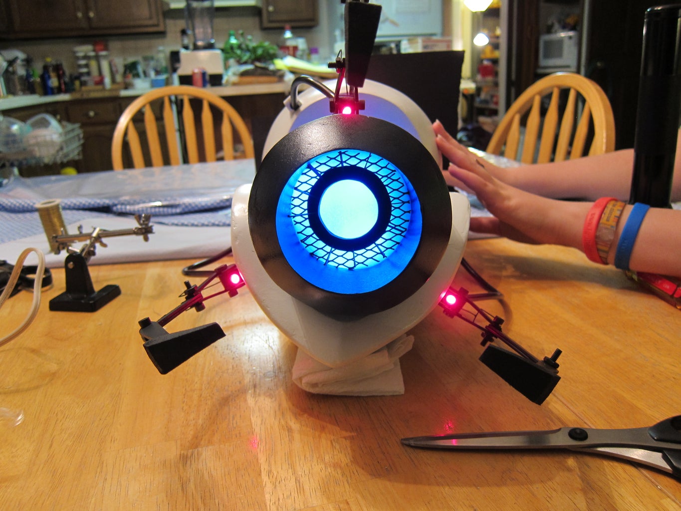
If you look into the front of the barrel you will see what looks like a grate and a sunburst-like black piece placed approximately 2” back from the lip of the barrel. To diffuse the light that shines out of the barrel, we layered thin sheets of packing foam directly behind the grating. You can probably get away with using whatever kind of foam you like… considering the stuff we used is unnamed and pretty generic.
In terms of what we'd like to redo about the gun, the barrel is the first on the list. What you see on the gun is actually incarnation #3, and rebuilding the entire thing from scratch is probably best. Getting the angles and different levels sanded was incredibly difficult and annoying. The barrel is probably the single piece that drew the most blood over the course of the entire project.
Step 12: Claws


It's Joe again!
This part is pretty straightforward. For the claws, print out the template and glue it to a piece of acrylic and go crazy with a scroll saw. These parts were a serious pain in the butt, though. They're small and the the drill doesn't like them. We broke 8 J-hooks and 5 small bars trying to make the claws. Unfortunately, I don't have any pictures of the funky triangular heads, but I do have a template for the pieces! Also, the template only has three small bars on it -- you'll need six to complete the arms.
We superglued the arm bases to the gun and just used the screw tension (8-32 torx screws) to hold the arms in position. It worked fairly well for what we needed, though we'll probably superglue the acrylic arm pieces together and keep the screws for looks. The red LEDs were by far the hardest to install -- it required running the wires through the completed gun and soldering them into the circuit while the gun was assembled. It was more of a time-crunch thing than anything else -- we really wanted to get this done by the LED contest deadline, so when we were finishing the gun at 10PM EST we needed a way to get the thing together enough to take completed pictures.
Shelley:
At the base of all three claws you will see a wire contraption that is (honestly) for decoration, and serves no structural purpose for the claws. I like to personally call these pieces Horse pieces! They look like little horses if you stand them up straight with all fours planted on the table.
Truthfully, we really don't know how much wire was actually used in the creation of these pieces. We actually made them before we made the claws, so we were very surprised that they were the perfect size in the end. If you want to use your personal judgment on how large they are, i don't think it would be a problem. In fact, I say go for it! Perhaps you think we made ours too large or small. Put your own personal flair on each piece!
If I had to venture a guess, though, as to how much wire we used, in total i would say approx. 22.5". The longer "horse legs" are approx. 4" and the shorter "legs" are approx. 3". The soldered-in piece connecting them (the "back" of the horse) is approx. .5" For the little circles at the "feet" (where the screw fits through) I simply used needle-nose pliers and slowly curved the ends of the wire piece into a circle.
Attachments
Step 13: Conclusion

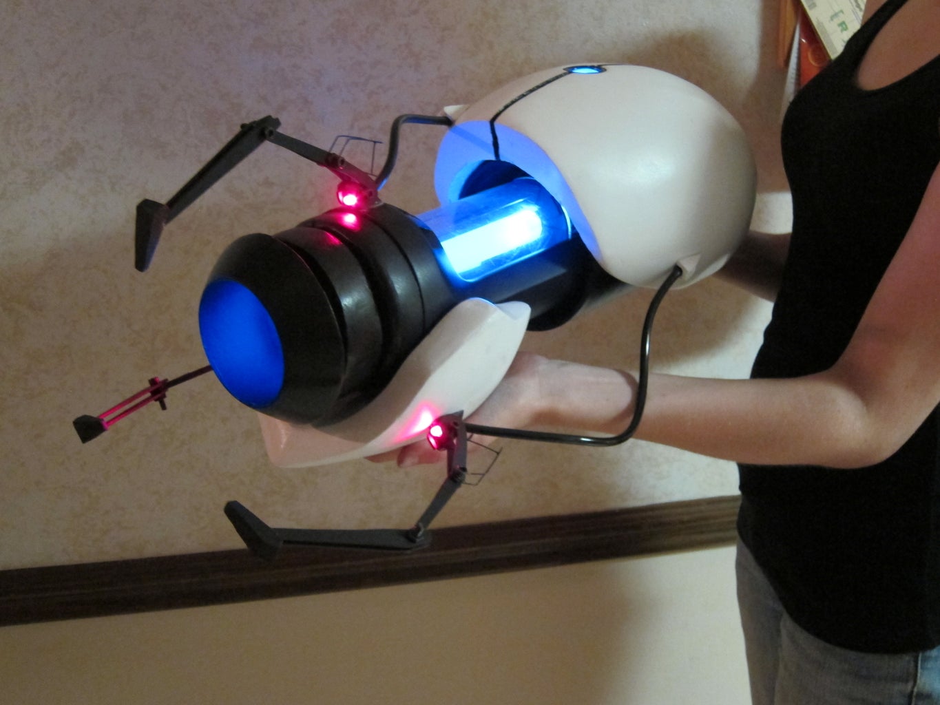
And there you have it! Hopefully you're now standing in front of your computer holding your very own Aperture Science Handheld Portal Device, getting ready to bellow a deep roar proclaiming your nerd-dom! Believe me, that's worth being excited over!
This, and the full costume, will be debuted at GenCon 2011 Indy in Indianapolis, IN, at the costume contest on August 6th. If you're in the neighborhood, come by and see us! We'd love to see you!!
If you like what you see, please take a moment and vote for us in LED contest! Any and all votes are greatly appreciated by the management.
This is our first instructable, although several more in the future may follow. If you've got any questions or comments, feel free to leave them and I'll answer as soon as possible. Thanks for reading and I hope you feel inspired to go create something awesome! :D
Mr. Krix, if you read this, thank you for doing what you do and posting little tidbits so some of us get to follow along. It's been a blast so far and we look forward to building more awesome stuff and just getting better from here. If you happen to find yourself by Indy in August, stop by and give us a shout! We'd love the opportunity to pick your brain for little tidbits and thoughts over lunch :)
The people responsible for this are Joe K. and Michelle S., with moral, emotional, and slave labor support from Jake B., Sam O., and Becca K. Y'all rock!
First Prize in the
LED Contest


