

Introduction: How to Make a Electronic Lock Using an Arduino UNO


This is a fairly easy project. You don't need to solder. Other than the Arduino UNO, all of the materials are easy to find and are not that costly. This project it is a fun way to lock your bedroom door, and is completely customizable. I have included the code, but to run it you need to have the Arduino software. Have fun!
Step 1: Gather the Materials

This picture shows the materials you will need.
The resistors are as follows
9 270 ohms(5% resistance)
3 10k ohms(5% resistance)
You will also need a power source. I hooked up my Arduino to my computer.
You will need a chord to connect the Arduino to the computer
Make sure everything works and then continue
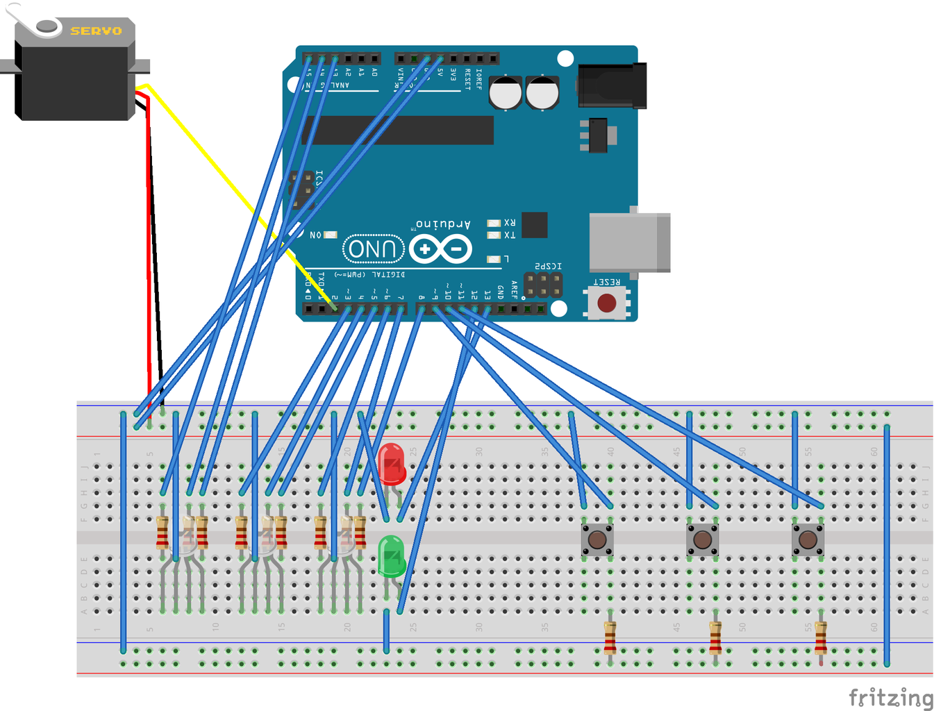
Step 2: Make a Diagram

This is how it will look. You can print out my diagram or make you're own. ( I used a program called Fritzing)
Step 3: Start Building
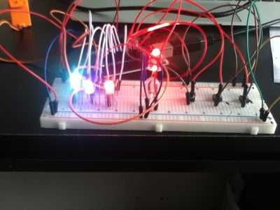
Now you are ready to assemble the lock.
I will show each new step in red wiring, and the old ones in blue.
Step 4: The Basic Wires
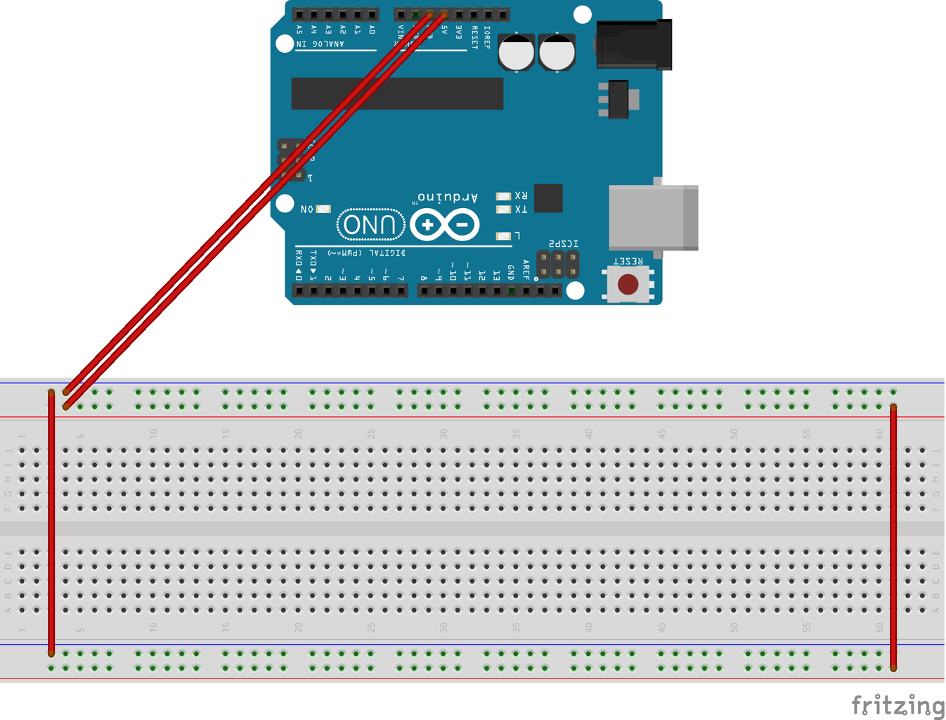
The first thing you need to do is connect the Arduino to the bread board. To do that, connect the ground(GND) of the Arduino to to the negative(blue) strip on the breadboard with a wire. Plug another wire into the 5 volt (5v) hole on the Arduino and to the positive (red) strip on you're breadboard. The first wire is typically brown or black, and the second red. Then run a wire from one side of the breadboard to the other side, both on positive. Do the same for the negative strip.
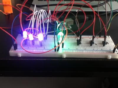
Step 5: RBG LEDs and the First Resistors

Now that the basic wires are in place, you need to connect the RBG LEDs. these LEDs change color and can be programed to do so. Unlike normal LEDs, they have four legs.
These LEDs will be what changes when you type in the code.
The first thing to do is to place the resistors. You will need nine resistors with 270 ohms each and a 5% tolerance. The four color stripes are red, purple, brown, gold.
Place them like shown, and make sure to have them make a bridge over the gap in the center of the breadboard.
Next you need the wires. You will need three relatively short wires. They go on the top half of the breadboard in-between the first and second resistor. The other end attaches to the negative row at the top of the breadboard.
Now the LEDs. If you look at the legs, you will notice that one is significantly longer that the rest. When you put you're LEDs in the breadboard, you want each leg to go into one of the holes in the same column as the resistors and wires, like shown in the picture. The longest leg, the common cathode, to be in the column with the wire, not the resistors.
When you are done, move on to the next step.
Step 6: Connecting the RBG LEDs to the Arduino

For this step you will need nine wires. It helps to have them all be the same color.
All you have to do is connect these wires into the following holes. Take a look at the picture.
Double check then continue to the next step.
Step 7: Right and Wrong

This step is about the LEDs that indicate if the password is right or wrong. The red LED will light up until the correct combination is typed in, then it will be replaced by the green LED.
The first thing to do is to put the LEDs in the breadboard, the red on the top and the green on the bottom. Remember to put them on different halves of the breadboard. The long leg should be on the right hand side.
Next you need to connect the LEDs to the negative row at the top and bottom of the breadboard. Use a short wire.
Then take two longer wires and connect one end of each to the long leg of the LED. Place the wire directly above or below the leg, in the same column. The other ends of the wires connects to the Arduino. the red LED wire goes to hole 13(digital) and the green wire goes to 12(digital).
When you have done this step, move on.
Step 8: Add in the Button

In this step you will add the buttons onto the breadboard.
you will need three push buttons, three 10K ohms resistors(brown, black, orange, gold) and six wires.
First you need to make a bridge over the gap in your breadboard using the push buttons. Each button has four legs.
Next place your resistors. One leg goes beneath the bottom right leg of the push button, and the other goes to the positive row at the bottom of the breadboard. Do this with all three resistors and all three push buttons.
Then take three short wires. one end of each goes above the upper left leg of each push button, and the other end of the wire connects to the negative row at the top of the breadboard.
The last three wires connect the push buttons to the Arduino. One end of each wire goes above the upper right leg of the push button, the other end of the wire goes int to Arduino. The wire for the first push button goes into hole 9, the second goes into hole 10, and the last goes into hole 11.
When you are all done, check your work and then move on.
Step 9: Make It Move
This is the final step where you will build. You need to add the motor.
You will need your three final wires for this step.
Your motor should have holes for three wires, and the wires coming out of the motor should be orange/yellow, red and brown/black
Run a wire from the red wire on the motor to the positive row of the breadboard.
Run a wire from the yellow/orange wire on the motor to the digital port 2 on the Arduino
Run the final wire from the black wire on the motor to the negative row of the breadboard.
Congratulations! Now you can move on to the software.
Step 10:

Now all you need to do is copy or download my code onto the Arduino software and run your lock!
The motor can be inserted in a door to lock it. this will require some drilling and cutting. Make sure you have permission to insert the motor into the door. This is optional.
Here is the code. Copy and past it into a new file in the Arduino software.
//--- bof RGBL - RGB Digital Preamble
//RGB LED pins
#include <Servo.h>
Servo myservo;
int pos = 0;
int ledAnalogOne[] = {A3,A4,A5};
//the three digital pins of the first digital LED 14 = redPin, 15 = greenPin, 16 = bluePin
int ledDigitalTwo[] = {3,4,5};
//the three digital pins of the first digital LED 14 = redPin, 15 = greenPin, 16 = bluePin
int ledDigitalThree[] = {6,7,8};
//the three digital pins of the first digital LED 14 = redPin, 15 = greenPin, 16 = bluePin
const boolean ON = LOW;
//Define on as LOW (this is because we use a common Anode RGB LED (common pin is connected to +5 volts)
int buttonA = 9;
int buttonB = 10;
int buttonC = 11;
int locked = 13;
int unlocked = 12;
// the secret numbers are the code. 111 is purple purple purple. change the number to change the code.
//the numbers corispond with a color. the list is below
int secretNumber1 = 1;
int secretNumber2 = 1;
int secretNumber3 = 1;
int key1 = 6;
int key2 = 6;
int key3 = 6;
boolean islocked = 1;
const boolean OFF = HIGH;
//Define off as HIGH
//Predefined Colors
// this is the list of colors
const boolean RED[] = {ON, OFF, OFF}; //4
const boolean GREEN[] = {OFF, ON, OFF};//2
const boolean BLUE[] = {OFF, OFF, ON};//1
const boolean YELLOW[] = {ON, ON, OFF};//6
const boolean CYAN[] = {OFF, ON, ON}; //3
const boolean MAGENTA[] = {ON, OFF, ON}; //5
const boolean WHITE[] = {ON, ON, ON}; //7
const boolean BLACK[] = {OFF, OFF, OFF};//0
//An Array that stores the predefined colors (allows us to later randomly display a color)
const boolean* COLORS[] = {RED, GREEN, BLUE, YELLOW, CYAN, MAGENTA, WHITE, BLACK};
//--- eof RGBL - RGB Digital Preamble
void setup(){
//while (!Serial);
// Serial.begin(9600);
//if trubleshoot, uncomment lines above
myservo.attach(2);
myservo.write(0);
for(int i = 0; i < 3; i++) {
pinMode(ledAnalogOne[i], OUTPUT);
//Set the three LED pins as outputs
pinMode(ledDigitalTwo[i], OUTPUT);
//Set the three LED pins as outputs
pinMode(ledDigitalThree[i], OUTPUT);
//Set the three LED pins as outputs
pinMode(buttonA,INPUT_PULLUP);
pinMode(buttonB,INPUT_PULLUP);
pinMode(buttonC,INPUT_PULLUP);
pinMode(locked, OUTPUT);
pinMode(unlocked,OUTPUT);
}
}
void loop(){
if (islocked == 1)
{
digitalWrite(unlocked, LOW);
digitalWrite(locked, HIGH);
}
else
{
digitalWrite(unlocked, HIGH);
digitalWrite(locked, LOW);
myservo.write(90);
}
setColor(ledAnalogOne, COLORS[key1]);
setColor(ledDigitalTwo, COLORS[key2]);
setColor(ledDigitalThree, COLORS[key3]);
if (digitalRead(buttonA) == LOW)
{
key1 = key1 + 1;
if (key1 == 8)
{ key1 = 0;
}
Serial.println("buttonA pressed");
Serial.println(key1);
}
if (digitalRead(buttonB) == LOW)
{
key2 = key2 + 1;
if (key2 == 8)
{ key2 = 0;
}
Serial.println("buttonB pressed");
Serial.println(key2);
}
if (digitalRead(buttonC) == LOW)
{
key3 = key3 + 1;
if (key3 == 8)
{ key3 = 0;
}
Serial.println("buttonC pressed");
Serial.println( key3);
}
if (secretNumber1 == key1 & secretNumber2 == key2 & secretNumber3 == key3)
{ islocked = 0;
}
else { islocked = 1;
}
delay(1000);
}
/* Sets an led to any color led - a three element array defining the three color pins (led[0] = redPin, led[1] = greenPin, led[2] = bluePin) color - a three element boolean array (color[0] = red value (LOW = on, HIGH = off), color[1] = green value, color[2] =blue value)*/
void setColor(int* led, boolean* color){
for(int i = 0; i < 3; i++) {
digitalWrite(led[i], color[i]);
}
}
/* A version of setColor that allows for using const boolean colors*/
void setColor(int* led, const boolean* color) {
boolean tempColor[] = {color[0], color[1], color[2]};
setColor(led, tempColor);
}
Then plug your Arduino into your computer and run the code!
About the code:
the lines :
int secretNumber1 = 1;
int secretNumber2 = 1;
int secretNumber3 = 1;
are the code. there are notes above these lines describing how to use it:
// the secret numbers are the code. 111 is purple purple purple. change the number to change the code.
//the numbers corispond with a color. the list is below
the colors are:
Red= 4
Green = 2
Blue = 1
Yellow = 6
Cyan = 3
Magenta = 5
White = 7
Black(off) = 0
You can set the colors, but the lights don't start at #! see if you can figure out what it starts at!
If you are having problems, try jiggling the buttons a little while pressing them.
If you have any questions, ask me at ava2000c@gmail.com or comment.
Have fun!
- Shadow513

Participated in the
Full Spectrum Laser Contest

Participated in the
Arduino Contest


