

Introduction: How to Use Serial Peripheral Interface


Any two electronic components that are connected together need to communicate with one another in some fashion. Sometimes it is as easy as giving the component a high or low voltage to get it to do what you want it to do, but most of the time more finesse is required.
One of the more popular communication styles, or protocols, is Serial Peripheral Interface (SPI). In this Instructable, I'm going to explain what SPI is, some of the theory on how it works, and the more important bit of how to actually use it on a microcontroller (both with and without a library).
Step 1: So, in a Nutshell, What Is SPI?

SPI is a communication protocol, originally developed by Motorola, as a way to transmit information between two electronic devices. It is a full duplex protocol, meaning that the two devices are able to "talk" to each other at the same time.
These two devices are designated as a "master" device and a "slave" device. The master device is the chip that always initiates each conversation and controls the pace at which the conversation takes place. The slave device only every sends and receives information (simultaneously) at the master's request.
Step 2: How Does the SPI Communication Take Place?

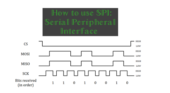
To have the communication between two devices work, there are four wires that are used: a Chip Select wire, commonly labeled as CS or SS (for slave select), a Master Out Slave In data line (MOSI), a Master In Slave Out data line (MISO), and a Serial Clock line (SCK).
The CS line is pulled low by the master device to indicate with the slave on the other side that it wants to communicate with it. Because this is an individual wire that is given a "LOW" voltage signal, this means that the master can actually control multiple "slaves" by driving their particular wire low.
The MOSI and MISO data lines do what you have likely already guessed; these are the two lines that allow SPI to be full duplex. Bits of data, in the form of a high or low voltage signal, is transmitted in one direction or the other between the two devices depending on which data line we are looking at.
The SCK line controls the pace at which the bits of data on the MOSI and MISO lines are transmitted. Like the CS line, the SCK line is controlled by the master and is driven in a high and low cycle to create "clock pulses" to control when a bit of data is to be transmitted across the lines. SPI can be configured to have the data transmit as the clock is going high or when it is going low; more on that later.
Step 3: You Keep Saying "bits" of Data

Indeed I am. SPI is designed (and required in order to truly be SPI) to work in byte sized communication chunks with eight bits to a byte. So, for every data transfer, there will be 8 clock pulses and 8 data transfers that will happen on the clock and two data lines.
However, there are some devices, such as the Analog Devices AD5628 chip present on Digilent's PmodDA4, that use Serial Peripheral Interface but say they transmit 12 bits of data rather than the 8 bits of data. Although this seems to be impossible since you cannot use the SPI protocol to transmit 8 bits and then only just 4 bits of data, the solution is found when we take a deeper look at the datasheet for the chip. After a bit scrolling we can see that the shift register for the DAC is actually 32 bits long (on page 22). This can nicely be split up into four individual 8 bit transfers.
Step 4: How Do We Transfer This Data?


Unlike other communication protocols, SPI is rather versatile in the fact that it is able to transfer data in a variety of ways. Depending on how each chip wants to receive the data, information can either be sent with the most significant bit (MSB) first or the least significant bit (LSB) first.
But the real versatility comes with the four different SPI clock modes that are available to choose from. These modes adjust if the clock signal starts at a high or low voltage value and if bits of data are transferred as the clock signal transitions to its high state or transferred as the clock transitions to its low state. The configuration of each of these clock modes are outlined in the table above. Again, each of these modes are chosen based on how the device expects to receive the information.
So, if we wanted two devices to send to each other a value of 210 via SPI, with the most significant bit first and the data transferred on the falling clock edge, we would first have the master bring the chip select line low, then bring the clock signal high, have each device "load" the appropriate bit onto the data lines, and then have the master bring the clock signal low in order for both devices to "collect" the bit of data that was on the line. This would be repeated until all the bits have been transferred and then the master would finally bring the chip select line high again to end the communication.
Step 5: What About Receiving the Data?
What you need to do in order to properly receive the data depends on what type of component is receiving the data. If you are having the master device (typically some form of a microcontroller) send information to another device that is not a microcontroller and just a small chip that only does one thing and never respond back to you (like produce analog voltage signals in the case of Analog Devices AD5628), then you as the user creating the circuit would generally not need to do anything. Just make sure that you are sending information to the device in the format that it wants to receive it in.
If you are hoping to receive feedback from a device (or are sending information to another microcontroller which you need to program to properly receive and interpret the incoming information), there are two different things that you may need to do. If the SPI library that you are using supports receiving (and returning) the 8 bits of data all in one piece, such as the SPI library for chipKIT/Arduino, then you may simply receive and store the information all in one piece into a variable in whichever way is appropriate for the coding language that you are using.
If you are not using a library for SPI, you will have to collect the individual bits of information and subsequently "mesh" them together. This is (probably) most easily done by receiving the bits of information in an array.
Step 6: Some Other Things to Consider

Although it may seem like SPI is done a certain way and works consistently, this isn't always the case. When attempting to use the master device to communicate with it's slave chip, there is the possibility that there isn't a slave device on the other end of the wire; the electronic chip that is the master device has no way to physically know if it is connected to a different chip via a wire.
Additionally, a lot of the code that may be used in SPI is solely for the SPI libraries. Some of the configurations, such as if the most or least significant bit should be sent first or when it should be sent on a clock cycle, are purely handled by libraries. However, it is also possible to perform the SPI protocol "manually". After all, all of the signals that SPI uses are just that; high and low voltage signals. So, as long as you connect the pins that the master is using to send out voltage signals are connected to the correct pins on the "slave" device, you could accomplish communicating by "SPI" without actually using the designated SPI pins.
Naturally, it will likely be faster (both in typing and actual speed) to use the SPI library, but it's good to know that all communication, SPI or otherwise, is in all reality just voltage signals.
Step 7: Running SPI: Without a Library
While theory is nice, I personally also find it more helpful when I see an actual example of what something would look like in code. This will be without using a predefined SPI library, since I think it is a little more helpful to see when each part of the SPI protocol occurs. The code itself (provided in the text file below) is based off Digilent's uC32, a powerful Arduino compatible microcontroller.
Attachments

Step 8: Running SPI: With a Library
You can also use SPI with an appropriate library. This method (not surprisingly) drastically cuts down on the amount of code that you as a user would need to type, but at the same time is somewhat abstract by nature. Unless you already know what each of the commands do internally, there is no easy way to figure out what is going on just by looking at it.
Attachments
Step 9: Some Final Thoughts
As I mentioned before, SPI is one of the more popular communication protocols that are used in the electronics world, but don't get the impression that it is the protocol to use; many other protocols like I2C, UART, USB, and even simple general purpose input/output (GPIO) pins have their own strengths and weakness for communication. If you want to see SPI being used to blink some LEDs (since that's always a great way to go), check out my Instructable on DACs here.
Feel free to ask me any questions that you have and I will do my best to answer them. Check out what else the Digilent team is up to at our blog!

![Tim's Mechanical Spider Leg [LU9685-20CU]](https://content.instructables.com/FFB/5R4I/LVKZ6G6R/FFB5R4ILVKZ6G6R.png?auto=webp&crop=1.2%3A1&frame=1&width=306)


