

Introduction: I2C Relay Board


Relays are one of the most common interfaces between a micro controller and the outside world. It provides electrical isolation between the low voltage circuits of the micro controller, and the loads.
So why this funny I2C Relay Board, you might ask....
With this instructable, I will try to give some of my reasoning behind the design of the I2C Relay Board.
Please enjoy, and any feedback is welcome.
Step 1: Normal Way to Drive a Single Relay

Normally, with a circuit driving only a minimum number of relays, the best way is to use a transistor driver circuit as shown. It is simple, low cost, and effective.
The resistors provide pull-down to ground, and transistor base current limitation.
The transistor is used to increase the current available to drive a relay. With only 1mA drawn from the micro controller pin, the transistor can switch a load of 100mA. More than enough for most types of relays.
The diode is a fly-back diode, protecting the circuit from high voltage spikes during relay switching.
The added advantage of using this circuit, is that the relay operating voltage can be different from the voltage of the micro controller. Thus, instead of using a 5V relay, one can use any DC voltage of up to 48V.
There is one drawback. Although the circuit only use 4 components, it all adds up quickly if more than about 4 relays are needed. So what to do if you want to drive 8 relays, but want to keep the PCB size as small as possible?
Step 2: Introducing the ULN2803


The more relays a project requires, the higher the component count. This will make the PCB design more difficult, and might use up valuable PCB space. But using a transistor array, like the ULN2803, will definitely assist in keeping the PCB size small.
The ULN2803 is ideally suited for 3.3V and 5V inputs from a micro controller, and can drive relays up to 48V DC.
This ULN2803 has 8 individual transistor circuits, each circuit fitted with all the components required to switch a relay.
Attachments

Step 3: What We Have Achieved So Far


By using the ULN2803 driver, we reduced the component count to drive 8 relays from 32 components, down to a single component.
This will make the PCB design much more simpler, and reduce the overall PCB size.
Step 4: Connecting Relays to a Project Using ULN2803


This shows a project that drives 16 relays. As can be seen, the space taken by the ULN2803 drivers are minimal, and the pin layout of the ULN2803 made it very simple to incorporate on the PCB.
The headers to the right of the ULN2803 are used to connect to each relay. This makes the relay PCB simple, with only one supply connection, and one connection per relay.
So you may ask, is there any way to improve on this design...
Step 5: Intruducing the Microchip MCP23017 I/O Expander


The MCP23017 from MicroChip is an I/O Expaner IC, that adds 16 additional I/O ports to a micro controller. Each of the MCP23017 pins can be configured as an Input or as an Output. The MCP23017 is controlled via the I2C bus, and with programmable addressing on the MCP23017, up to 8 MCP23017 IC's can be connected to a project. This adds up to a total of 128 extra I/O pins.
Looking at the project where 16 relays are controlled, the number of wires between the main PCB and the relay board totals 17 wires - one relay positive supply, and one wire per relay.
Using the MCP23017, the wiring between the main PCB and relay board can be reduced to only 5 wires:
- relay positive supply
- +5V for MCP23017
- 0V
- SDA (I2C bus)
- SCL (I2C bus)
Best of all, to control the maximum of 128 extra I/O ports, it still only requires the same 5 wires from the main PCB. This makes for a simple and neat main PCB design, and reduces internal project wiring to a minimum.
Attachments
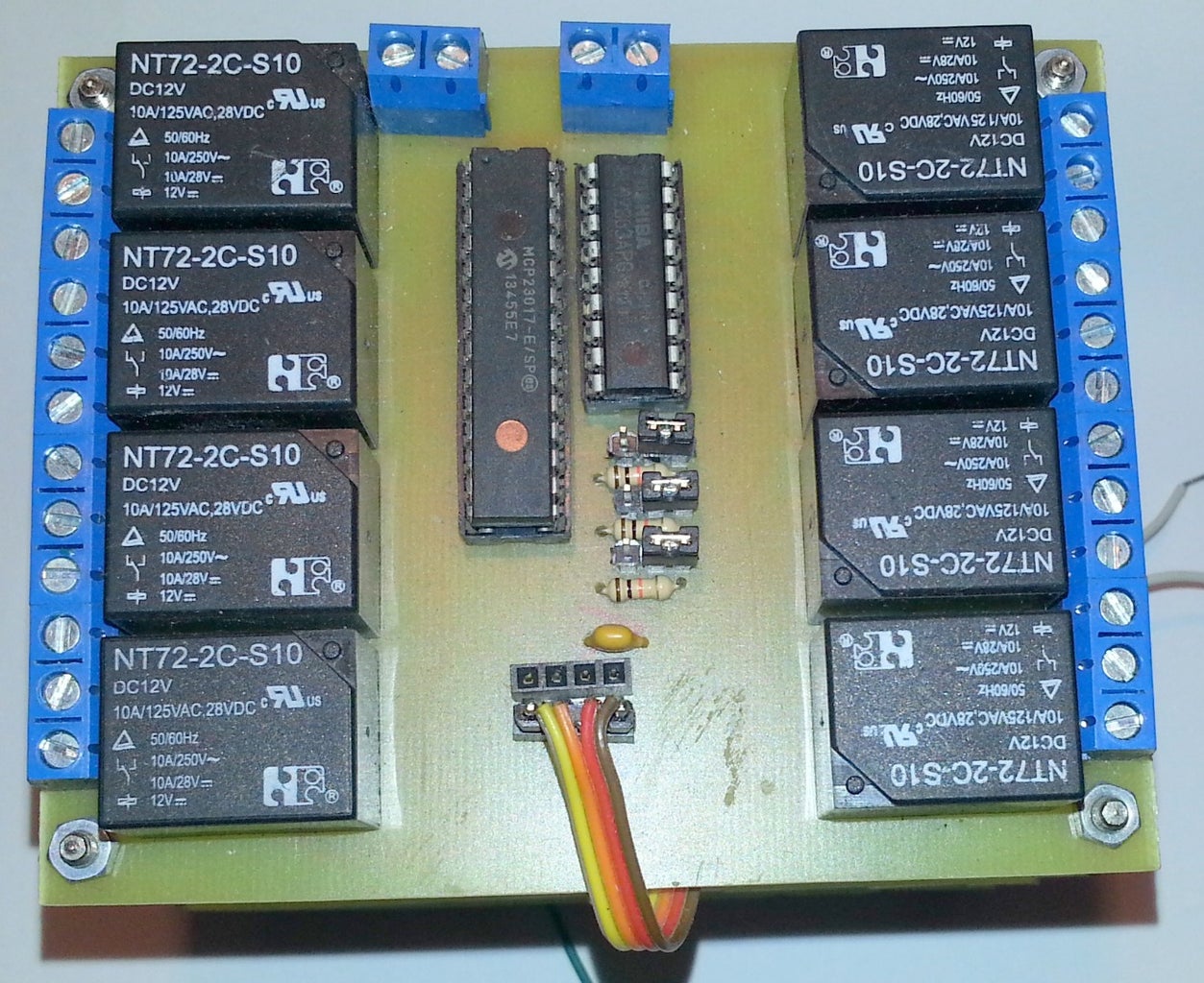
Step 6: Designing of the I2C Relay Board


PCB Design software limitation
I am using the free version of Eagle for all my PCB designs. The software has only one limitation, and that is that the board size is restricted to 100mm x 80mm. For all my recent projects, this was acceptable.
Designing a single relay board with 16 relays and their screw terminals, was not possible on a 100mm x 80mm PCB. But it was possible to fit 8 relays with their terminal screws, a MCP23017 and ULN2803 on a single board. Instead of a single PCB, the design was changed to two identical PCBs. The only disadvantage with this option, was that instead of using all 16 I/O pins from a single MCP23017, each board had to be fitted with it's own MCP23017, and using only 8 of the 16 I/O ports.
Component selection
The design must be build using only standard through-hole components.
Connecting multiple I2C Relay Boards
The MCP23017 has three address lines (A0, A1 and A2), and each I2C Relay Board must have a unique I2C address. For easy addressing, header pins were added to set the address of each I2C Relay Board. With this option, up to 8 I2C Relay Boards can be connected to a project, to control a total of 64 relays.
Supplying power to the relays
With up to 64 relays that can be connected to a project, it is clear the power supply needed for the relays can no longer be taken directly from the main project PCB. Therefore, supply to each individual I2C Relay Board is done via screw terminals. To make it easy to loop the supply between I2C Relay Boards, two sets of screw terminals were
added.
Relay operating voltage
As there is a large selection of relays available, the design had to cater for different relay operating voltages. By using the ULN2803, the relay voltage can be between 5V and 48V DC. This makes selecting relays easier.
Connecting a load to the relays
A set of 3 screw terminals per relay allows easy connections the relay contacts (Common, Normally Open, Normally Closed). There is no common connections between the 8 relays, allowing maximum connection flexibility using the I2C Relay Board.
Connecting the I2C Bus
Connection of the four I2C Bus wires is done using headers. Again, two rows of headers were added for easy connection of multiple I2C Relay Boards.

Step 7: Cost and Design Breakdown

Using the project where I had to control 16 relays , the different designs can now be compared
Transistor design
32 Resistors, 16 Diodes (1N4007), 16 Transistors (BC109)
Total number of components excluding relays: 64
Total cost of components, excluding relays : ZAR116.96
Pros:
Standard everyday components
Cons:
Difficult PCB layout
17 wires between project and relays
ULN2803 design
2 x ULN2803
Total number of components excluding relays: 2
Total cost of components, excluding relays : ZAR18.24
Pros:
Minimum components
Easy PCB layout, and reduces overall PCB size
Cheapest option
Cons:
17 wires between project and relays
I2C Relay Board design
2 x ULN2803, 2 x MCP23017, 6 x 3-pin headers, 6 x mini-jumpers, 6 x resistors
Total number of components excluding relays: 22 (4 without the address selection headers)
Total cost of components, excluding relays : ZAR78.00
Pros:
Easy to connect multiple I2C Relay Boards to project
Only 6 wires between project and relays
Cons:
Not the cheapest option available.
Step 8: Connecting the I2C Relay Board


The project shown, uses 16 relays, so it contains two I2C Relay Boards. The address of the boards are set to 0 and 1 respectively. As can be seen, the connections between the different PC boards are now kept to a minimum.
Simply connect the +5v, 0V, SDA and SCL lines to an Arduino I2C Bus using ribbon cable.
Connect the required V-Relay to the board.
Step 9: Arduino and the I2C Relay Board
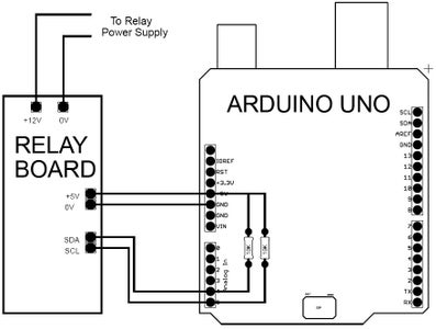

Connect the board to your Arduino as shown.
Below is a simple sketch for using the I2C Relay Boards.
In this sketch, only the "wire" library is used. Due to the easy comminucation on the I2C Bus, all comms to the MCP23017 is included in the sketch.
<p>#include   <Wire.h>   // needed for I2C operation<br></p><p>void setup() {
  //start I2C communications
  Wire.begin();</p><p>  // Setup relay boards
  SetupRelays();
}</p><p>void loop() {
  // put your main code here, to run repeatedly:

  for (byte relaydata = 0; relaydata <= 255; relaydata = relaydata + 1) {
    // write data to cards 0 .. 7 relays
    WriteRelays(0,relaydata);    // write data to relay card 0
    WriteRelays(1,relaydata);    // write data to relay card 1
    WriteRelays(2,relaydata);    // write data to relay card 2
    WriteRelays(3,relaydata);    // write data to relay card 3
    WriteRelays(4,relaydata);    // write data to relay card 4
    WriteRelays(5,relaydata);    // write data to relay card 5
    WriteRelays(6,relaydata);    // write data to relay card 6
    WriteRelays(7,relaydata);    // write data to relay card 7
    delay(1000);
  }
}</p><p>//++++++++++++++++++++++++++++++++++++++++++++++++++++++++++++++++++++++++
// Begin of MCP routines - no library needed
</p><p>//++++++++++++++++++++++++++++++++++++++++++++++++++++++++++++++++++++++++</p><p>void SetupRelays() {
  // Setup all possible relay cards (address 0 to 7)
  for (byte i = 0; i <= 7; i = i + 1) {
    MCP_Write(i, 0x00, 0b00000000);      //  set all pins to output
    MCP_Write(i, 0x12, 0b00000000);      //  set all outputs to off
  }
}</p><p>void WriteRelays(byte address, byte data) {
  // Write data to relays
  // --------------------
  MCP_Write(address, 0x12, data);
}</p><p>void MCP_Write(byte MCPaddress, byte MCPregister, byte MCPdata) {
  // I2C write routine
  // -----------------
  MCPaddress = MCPaddress + 0x20;    // 0x20 is base address for MCP
  Wire.beginTransmission(MCPaddress);
  Wire.write(MCPregister);
  Wire.write(MCPdata);
  Wire.endTransmission();
}
</p><p>//++++++++++++++++++++++++++++++++++++++++++++++++++++++++++++++++++++++++</p><p>// End of MCP routines
</p><p>//++++++++++++++++++++++++++++++++++++++++++++++++++++++++++++++++++++++++</p>
Enjoy !
Attachments
Step 10: Building and Selling This Project

If there is a company interested in building this I2C Relay Board, please do so. It would be great if this can be made available for hobbyist as a ready-made add-on.
s.


