

Introduction: Light Sensor Circuit


The circuit is a light sensor circuit. It can be employed to compare the light levels in an area. It uses a p-n junction photodiode as the light sensor and IC CA3140 as a voltage comparator.
In the circuit, a photodiode is connected in a reverse bias mode to the inverting pin (pin 2) of the op-amp. A variable resistor is connected to the non-inverting pin (pin 3) of the op-amp. The role of the variable resistor is to maintain a constant voltage at the non-inverting pin (pin 3) which can be changed as and when required by changing the resistance of the variable resistor. A led is connected at the output pin (pin 6) in forward bias through a resistor.
When light falls on the photodiode, the led glows dimly and when no light falls on the photodiode, the led brightly indicating the levels of darkness in the room.
Step 1: Materials Required:


Here's the list of the materials that you would require to make the circuit.
- PCB board
- IC CA3140
- LED
- Photodiode
- Resistors
- Variable resistors
- 9V batteries
- Battery connectors
- Wires
- Soldering Kit
Step 2: IC CA3140


The IC CA3140 works as a voltage comparator. In such a configuration, an op-amp compares the voltage levels between its inverting pin (pin 2) and the non-inverting pin (pin 3) and gives an appropriate high/low output. When the voltage at its non-inverting pin (pin 3) is greater than the voltage at its inverting pin (pin 2), the comparator returns a positive saturation voltage, +Vsat, whereas, when the voltage at its non-inverting pin (pin 3) is less than the voltage at its inverting pin (pin 2), the comparator returns a negative saturation voltage, -Vsat.
Step 3: Working


When the light is allowed to fall on thephotodiode, resistance of the photodiode decreases and thus the potential at the inverting pin (pin 2), which is equal to the potential across the photodiode, is low. When the light is not allowed to fall on the photodiode, resistance of the photodiode increases and thus the potential at the inverting pin (pin 2), which is equal to the potential across the photodiode, is high.
The resistance of the variable resistor is adjusted in such a way that the potential at the non-inverting pin (pin 3) lies midway of the two potential values at the inverting pin (pin 2).
When the light falls on the photodiode, the potential at the inverting pin (pin 2) falls below the potential at the non-inverting pin (pin 3). The comparator compares the two voltages and since the voltage at the non-inverting pin (pin 3) is greater than the voltage at the inverting pin (pin 2), the comparator returns a positive saturation voltage, +Vsat. Now, since the output pin drives at a positive saturation voltage, +Vsat, it draws a very small amount of current from the battery and thus the led glows dimly.
When the light is not allowed to fall on the photodiode, the potential at the inverting pin (pin 2) rises above the potential at the non-inverting pin (pin 3). The comparator compares the two voltages and since the voltage at the non-inverting pin (pin 3) is less than the voltage at the inverting pin (pin 2), the comparator returns a negative saturation voltage, -Vsat. Now, since the output pin drives at a negative saturation voltage, -Vsat, it draws a comparatively more amount of current from the battery and thus the led glows brightly.
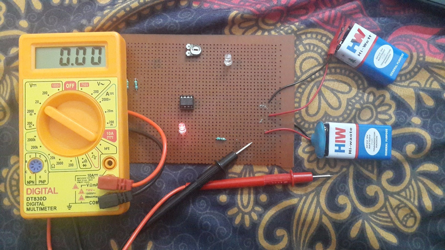
Step 4: Observations


Inverting pin (pin 2)
- Voltage when light falls on the photodiode = 0.08V
- Voltage when no light falls on the photodiode = 2.69V
Non-Inverting pin (pin 3)
- Voltage when light falls on the photodiode = 1.21V
- Voltage when no light falls on the photodiode = 1.21V
Output pin (pin 6)
- Voltage when light falls on the photodiode = 7.51V
- Voltage when no light falls on the photodiode = 6.69V
LED
- Voltage when light falls on the photodiode = 1.75V
- Voltage when no light falls on the photodiode = 1.81V
Resistor R3
- Voltage when light falls on the photodiode = 0.32V
- Voltage when no light falls on the photodiode = 1.08V
P.d. between pin 6 and +Vcc
- Voltage when light falls on the photodiode = 2.08V
- Voltage when no light falls on the photodiode = 2.9V
LED
- Current through the led when light falls on the photodiode = 0.34mA
- Current through the led when no light falls on the photodiode = 1.1mA
Step 5: Watch This Short Demonstration
This is the link to the video..
https://www.youtube.com/watch?feature=player_detailpage&v=ixthBtfoBBI
Thank You...


