

Introduction: Long Range Ultrasonic Distance Sensor


This Instructable demonstrates a method of increasing the measuring range of the popular HC-SR04 ultrasonic distance sensor.
The enhancement in range is based on reducing the 'field of view' (FOV) of the basic sensor by using it as a feed element for a parabolic dish.
No changes have been made in the electronics of the basic HC-SR04 sensor. However, a blanking circuit has been added externally so as to ignore the first reflection/distance from the feed element to the parabolic dish.
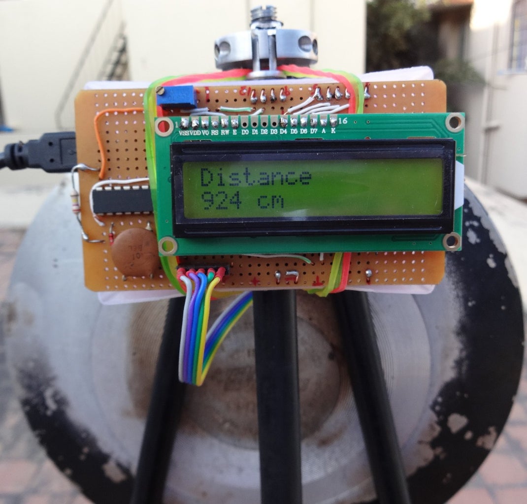
The HC-SR04 is connected to an Arduino uno which displays the measured distance on a standard PC1602 16X2 LCD display. The distance is also sent on the serial link through the USB connector.
For outdoor experiments the system was powered through the USB connector using mobile power bank.
A maximum distance of 9.24 meters was achieved in the experimentation as compared to the 4 meters specified for the basic sensor.
I wish to acknowledge useful inputs from Emil's Project Blog where he has provided an excellent tear-down of the HC-SR04 ultrasonic distance sensor:
Step 1: The Parabolic Reflector


The specifications of the HC-SR04 ultrasonic sensor indicate a measuring angle of 15 deg. When used as feed element for a parabolic dish, so that the dish is fully illuminated it needs to be placed at a sufficient distance from the dish. A shallow dish is required so that the focal length matches this requirement.
An old frying pan with a diameter of 250 mm and a depth of 16 mm is chosen as the parabolic dish. Standard calculations for sound in air at 40 kHz indicate a focal length of 24.4 cm and a FOV/ beam width of 2.31 deg.
The reduction in measurement angle/FOV from 15 deg to ~ 2.3 deg will be used to provide the increased measurement range.
The pan handle-arrangement is modified and a aluminum tube suitably bent is taped to the handle bracket to form the feed support beam. The HC-SR04 sensor is fixed along the center line of the parabolic dish at a distance of ~ 24 cm.
Step 2: Need for the Blanking Circuit


The HC-SR04 sensor outputs a positive going Echo pulse when triggered by a narrow positive going Trig pulse. In normal operation the width of the Echo pulse is proportional to the time required for the 40 kHz pulse train for the to-and-fro distance to the reflected object.
At a nominal sound velocity in air of 330 met/sec a 1 milli-sec pulse width would correspond to a range of 16.5 cm and a two-way travel of 33 cm.
Therefore with the feed distance of ~24 cm the distance would correspond to 1.45 milli-sec or 1450 micro-sec. Without providing a blanking circuit to ignore this shorter distance the longer distance from the parabolic dish to the reflective object cannot be determined.
Th blanking circuit shown is a simple mono-stable multi-vibrator circuit built using three . Schmidt- inverter gates. The output of the blanking circuit pulls the detection threshold low corresponding to high signal requirement for ~ 2.5 milli-seconds so that distances of ~ 40 cm are ignored.
This value should be larger than 24 mm but less than 48 cm so that the minimum distance from the front of the feed point can be measured.
Without the blanking circuit the distance is read as 23 cm.
Step 3: Modification on HC-SR04 for Blanking


After studying the circuit of the Hc-SR04 it is observed that the Threshold signal from Pin 9 of the OTP controller goes to Pin 2 of LM324 U2A through a 75 k Ohm resistor.
However, when we compare this with the actual HC-SR04 hardware we see that the LM324 is marked as U1.
Th blanking output of the additional blanking circuit is connected to Pin 2 of U2A as per the circuit diagram and Pin 2 of U1 as per the hardware.
There are normally 4 connections to the HC-SR04:: Vcc, Trig, Echo and Gnd. An additional wire marked Blank is now added as the 5th connection.
Step 4: Arduino Based Bread-Board and Schematic


The Fritzing diagrams show the Bread-Board and Schematic for the overall system
The connection to the Ultrasonic sensor and LCD are standard and well documented.
The prototype circuitry was wired on a perforated circuit board which forma shield for the Arduino uno.
The LCD was connected to the top of the board.
For outdoor experiments the system was powered through the USB connector using a mobile power bank.
The Fritzing project file including the Arduino code is attached.
The sketch as text file is also attached


Participated in the
Arduino All The Things! Contest


