

Introduction: Machining a PCB Using an Inexpensive CNC Machine


Introduction:
For this tutorial we are going to take a design that we made from EAGLE, use PCB-GCode and Autoleveler software to load it into our ZEN Toolworks Mach 3 CNC machine. What we can do is then create circuit boards using our own designs right before our very eyes.
Materials Needed:
- CADSoft's EAGLE software
- PCB-GCode Autoleveller
- ZEN Toolworks CNC machine with Mach 3 driver package.
- Mach 3 software installed to a Windows XP or 32 Bit Windows Vista or 7 Computer with a parallel printer port installed.
- Carbide End Mill 3.175mm, 30 degree cutting bit.
- One .7mm drill bit.
- Blank circuit boards.
- Eye protection.
- Double-sided tape.
Note:
This tutorial is going to presume that you have either already followed the tutorial on Designing an Arduino shield or already have a design made from EAGLE. While we are using the ZEN Toolworks 7 x 12 CNC machine with the Mach 3 driver package the principals that we are using should translate to similar CNC machines.
Step 1: Downloading and Installing Software
- You need to attain the above programs, EAGLE, PCB-GCode and Autoleveller.
- EAGLE can be attained at: http://www.cadsoftusa.com/download-eagle/
- EAGLE is a software that you have to pay for, but you can get a Freeware version that only allows up to 2 layers, which is enough to do most hobby circuit designs.


- PCB-GCode can be attained at: http://pcbgcode.org/read.php?12,803
- PCB-GCode is completely free
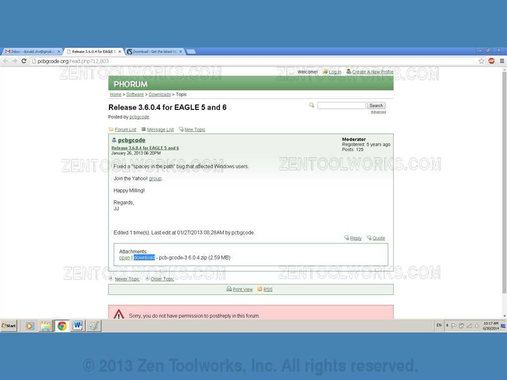
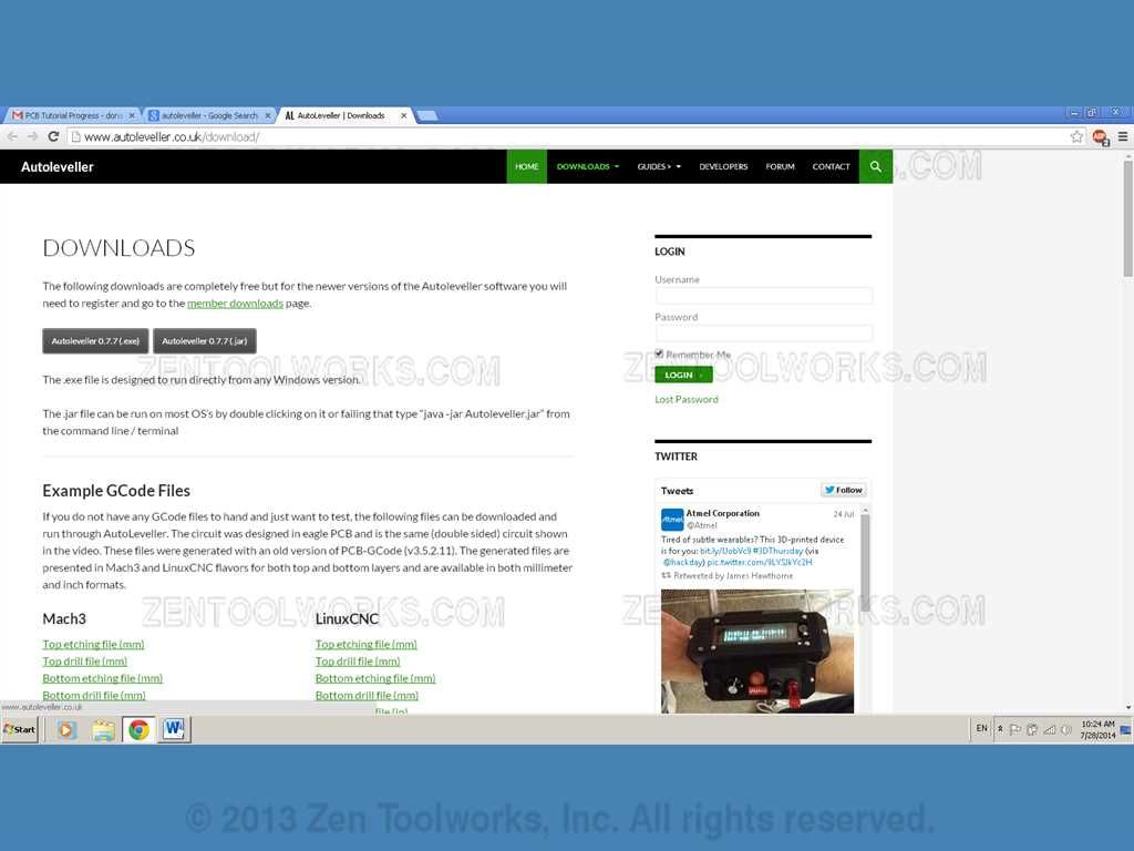
- Autoleveller can be attained at: http://pcbgcode.org/read.php?12,803
- Autoleveller is also free for the previous version which we are using in this tutorial.
- For this tutorial you will need to have EAGLE and Autoleveller installed.
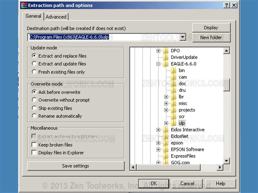
- Now for unzipping you need to unzip the folder in the proper directory for EAGLE to recognize its location. First unzip the folder to C:\Program Files (x86)\EAGLE-6.6.0\ulp
Step 2: Setup EAGLE CAD
- Now we need to open up EAGLE.
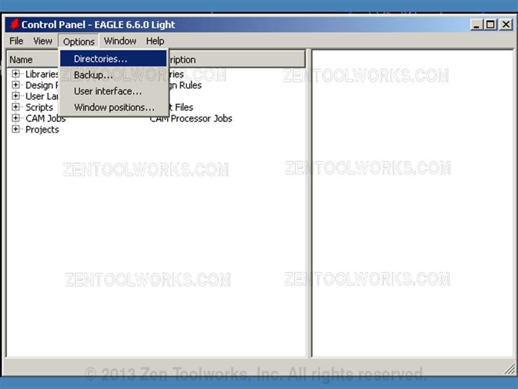
- This step is very important so that we can get the proper UDP at a later step. What we need to do is go into Options>Directories
- Now we need to insert a line in the User Language Programs that reads ;$EAGLEDIR\ulp\pcb-gcode-3.6.0.4 right after the previous line. ·
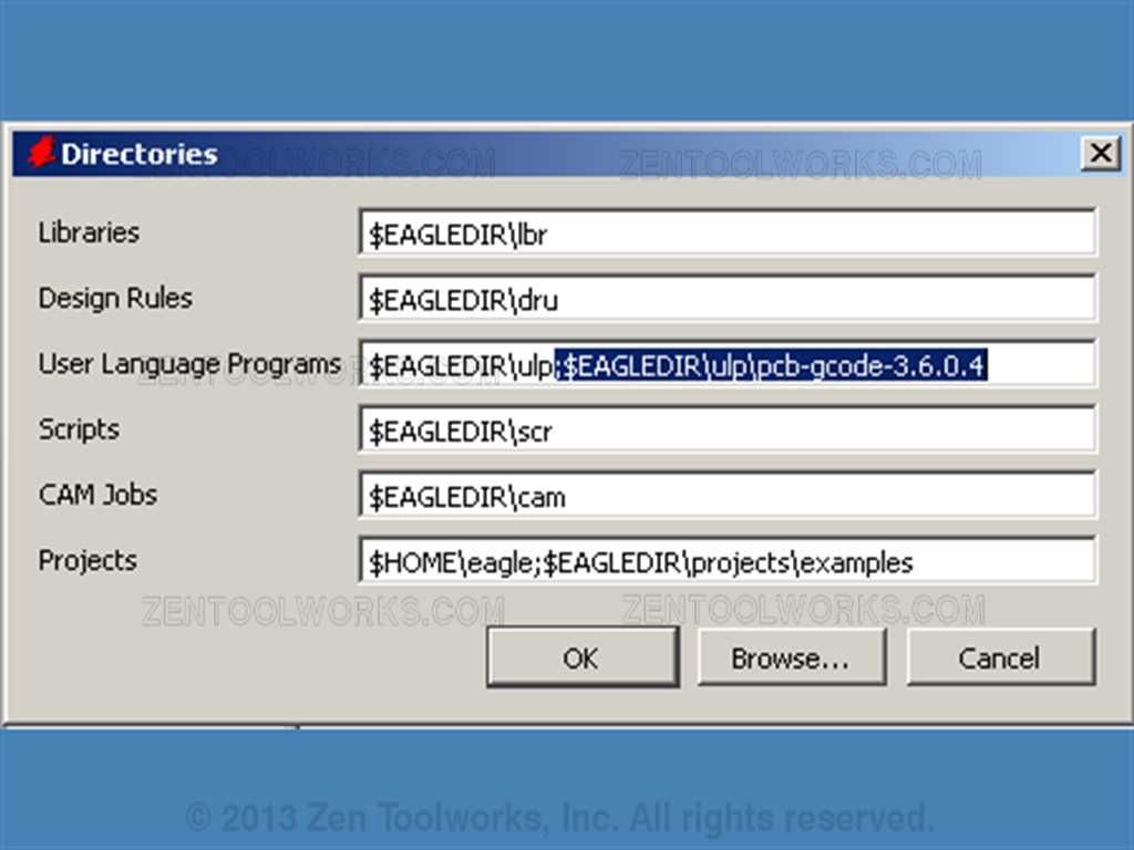
- This is vital as we need this line in so that the PCB-GCode can be used properly for our machine.
Step 3: Loading Our Circuit
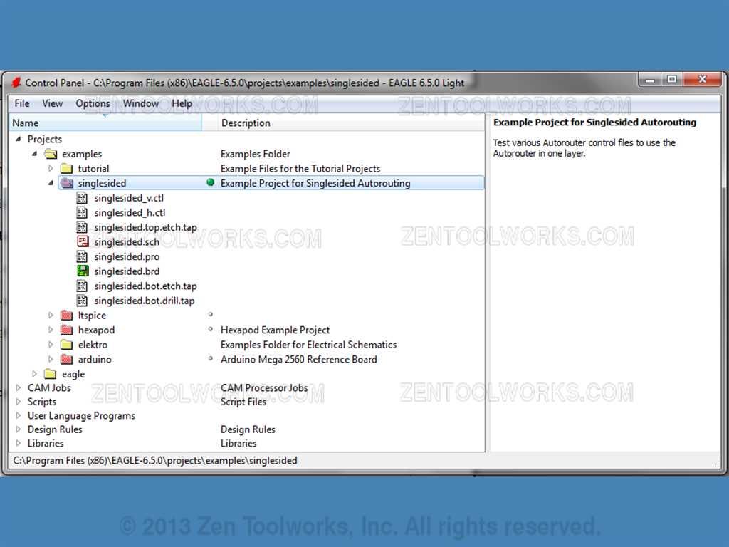
- For this tutorial we are going to use the circuit that was designed in EAGLE from our previous tutorial on designing an Arduino Shield in EAGLE.
- We open up the desired circuit board to work with.
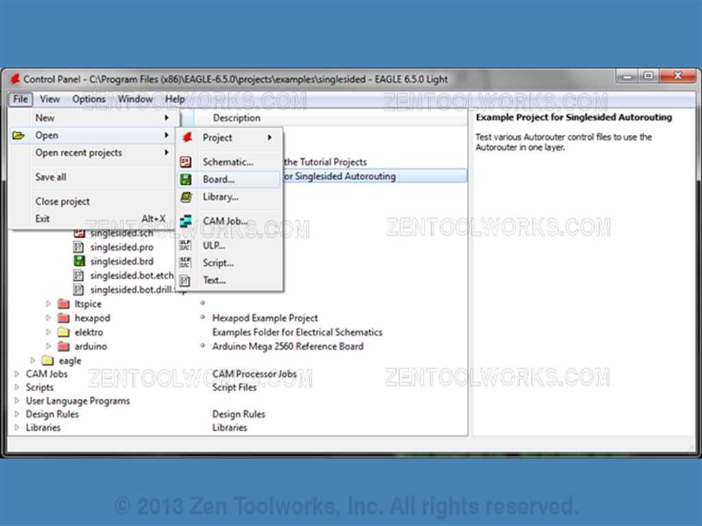
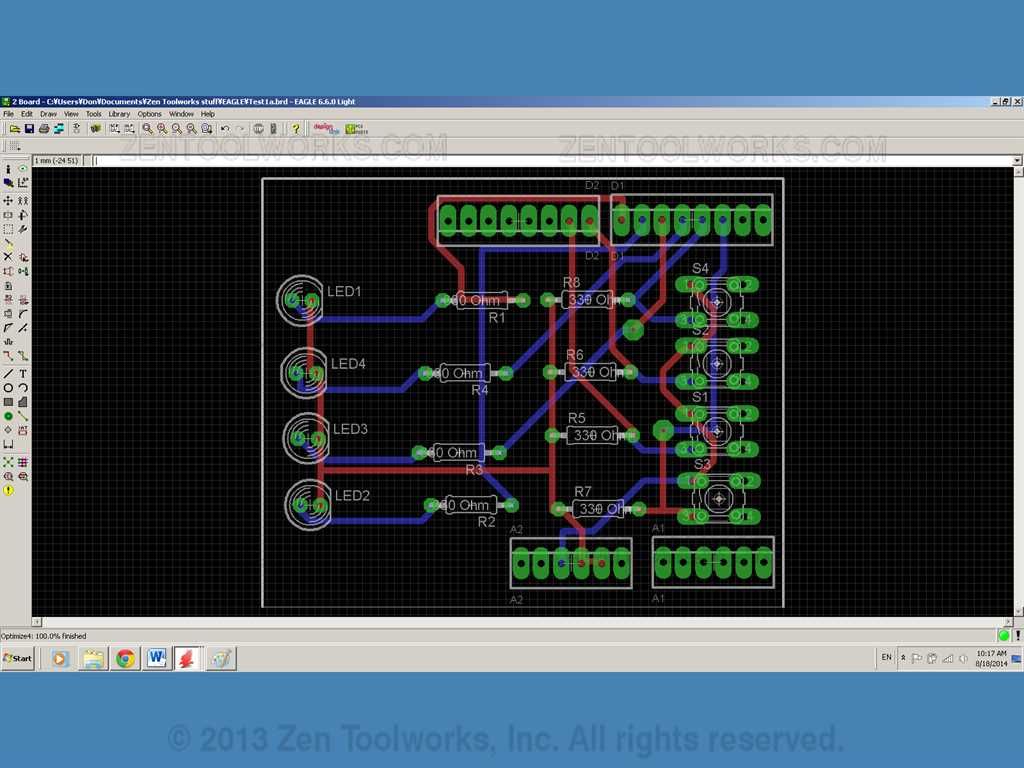
- Navigate to the desired circuit board and click open. In this case this would be my own Test1a board.
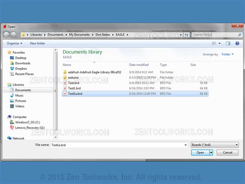
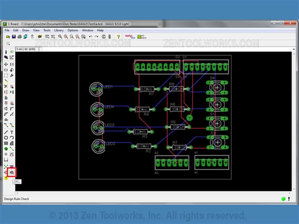
- Now our desired circuit should appear on our workspace.

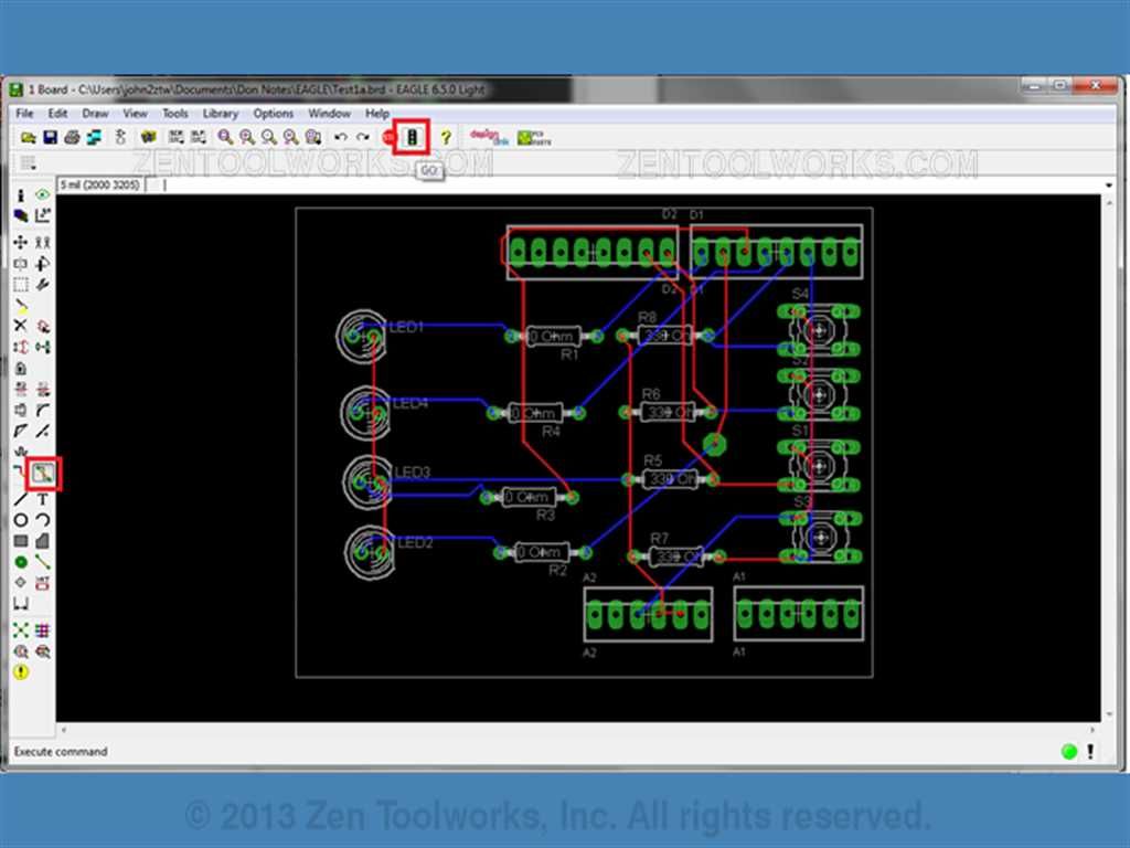
Step 4: Using DRC to Make Our Traces and Check Our Clearnances
- We are going to need to use EAGLE to enforce design limitations. We do this by pressing the DRC button on the side panel.
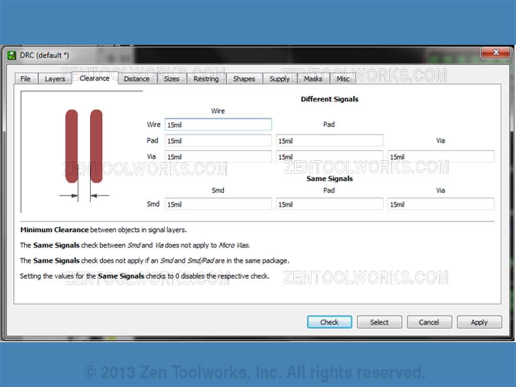
- We first click on the clearance tab.

- Next we need to change all of the options to 15mil as this setting seems to work well with the tip we are using for our CNC machine so we set this as our clearing width.
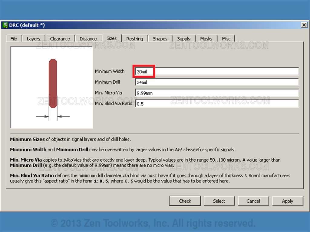
- You also may want wider traces you can accomplish this while we are in the DRC, click on the “Sizes" tab. Then change the size of the traces as big as you think you need. For this project we adjusted them to 30mil.
- Next you click “Check” to see what parts of your board are too close together.
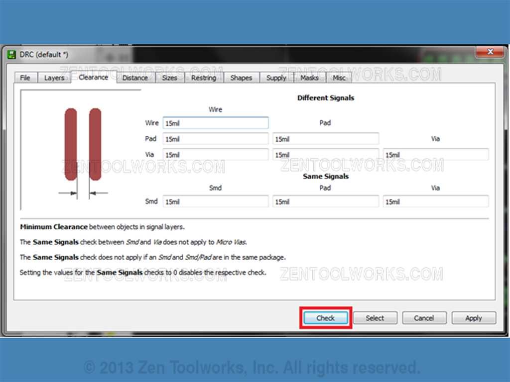
- You may get a list of errors like this:

- In which case you just need to adjust your circuit or you can have all of the wiring taken off using the Ripup command, followed by the stoplight button.
- Next you just use autorouter again to rewire your circuit with the bigger leads.
- Be sure to run the DRC and check for errors and adjust as needed. Once the DRC comes up clear we can move on to our next step.
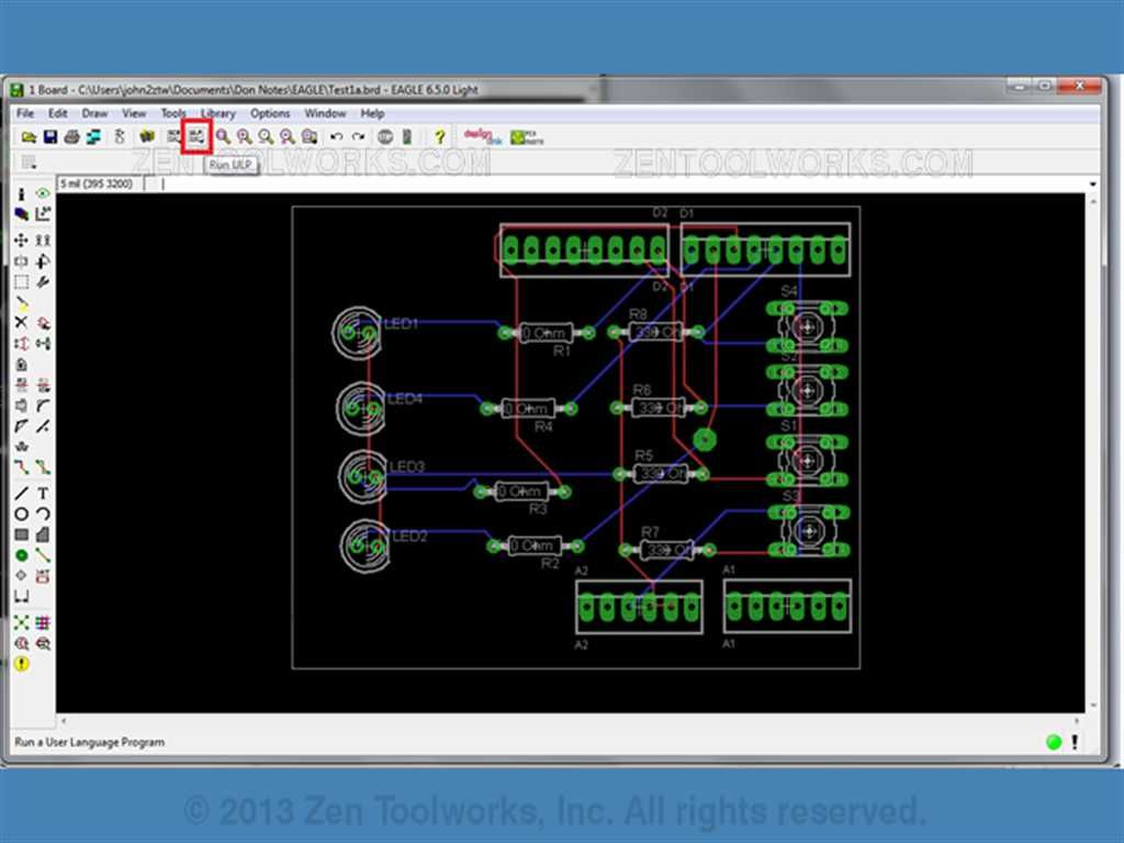
Step 5: PCB G-Code Setup and Outputting G-Code
- Now we have to run the ULP setup. The way we do this is to first click on the Run ULP button on the toolbar above our circuit design.
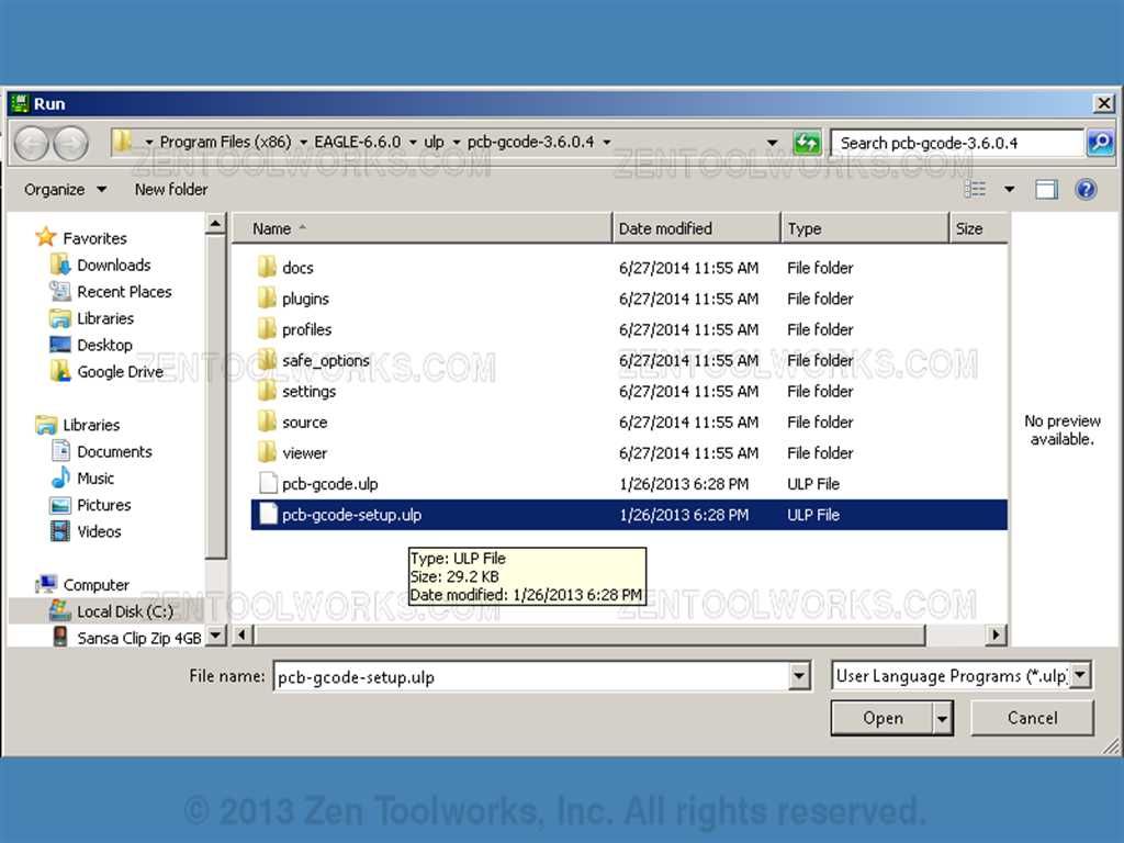
- We then navigate to our folder where we up the PCB-GCode files and look for the one called pcb-gcode-setup.ulp.
- You should get a screen like this:
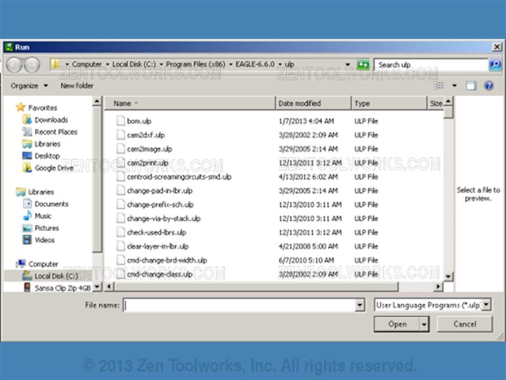
- Now you want to navigate to where you unzipped your PCB-GCode folder.
 ·
·
- Now we want to open our folder and click pcb-gcode-setup.ulp file. ·
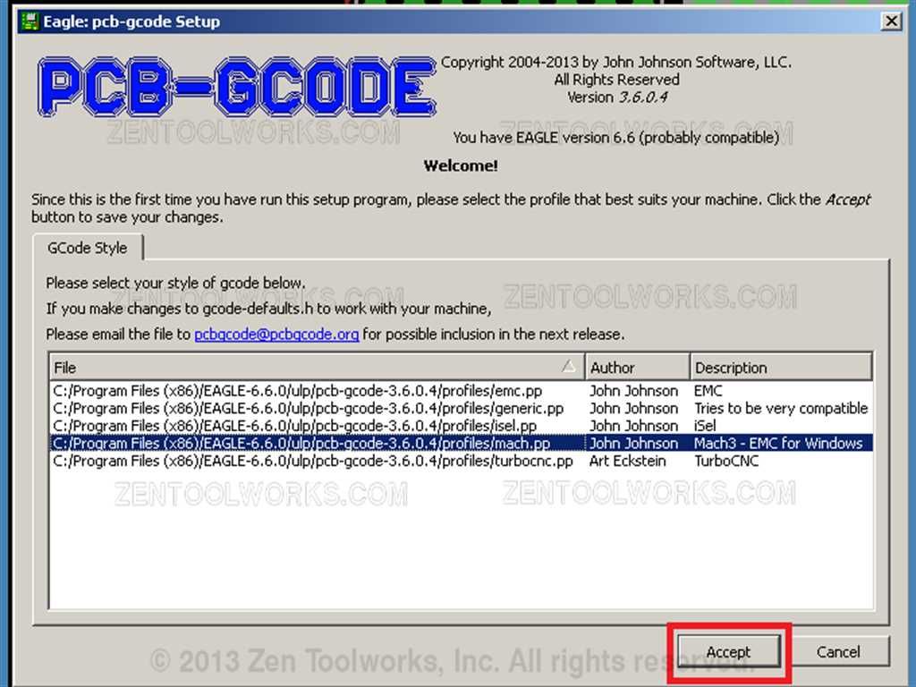
- You will see this screen if you are setting it up for the first time.
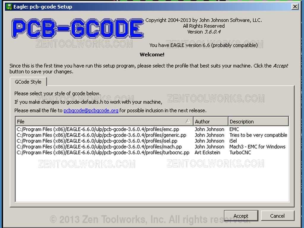
- For this tutorial we are using the Mach3 option as this is the CNC driver package we have for our machine. · So we select our GCode style from the options listed, and then click Accept.
 ·
·
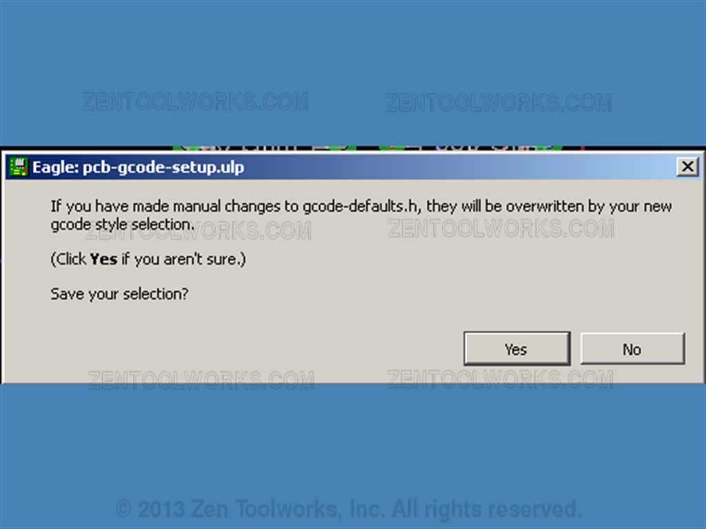
- You will get a screen like below, go ahead and click Yes.
 ·
·
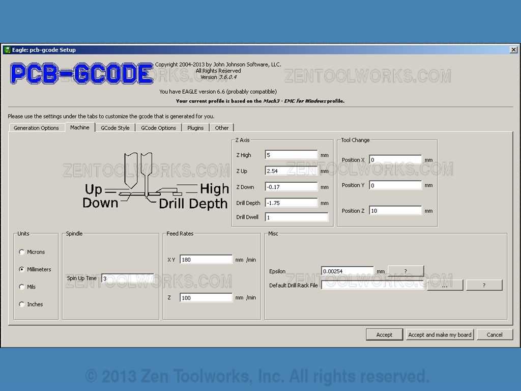
- You will now get the setup page of our PCB-GCode.
 ·
·
- We need first change from inches to millimeters; we do this by going to the Machine tab then clicking on millimeters. · Then we need to adjust the values for our cutting bit. For this exercise with our mach3 machine we are going to use these values:
 ·
·
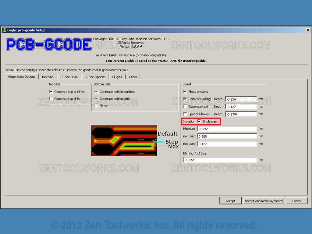
- We need to also change our Z axis options to reflect our bit that we wish to use for the cutting out our PCB board. The board we are using is no more than 1 millimeter thick so we need to have the drill depth more than -1mm. The reason we need a negative value is that we are using the surface of the board itself as our Zero for the Z axis. We do want our drill to pierce the board where we want to make our solders for our shield. · We also need to change the options on the Generation Options tab what is shown for our particular bit:
 ·
·
- Since our options and bit allow us to do a single pass we click on the check mark to do a single pass. · Now we click Accept and make my board.

Step 6: Autolevelling Our G-Code
- Once you hit the “accept and make my board” button the program will draw up some previews of your board along with making the various extensions needed for autoleveller in the GCode. ·
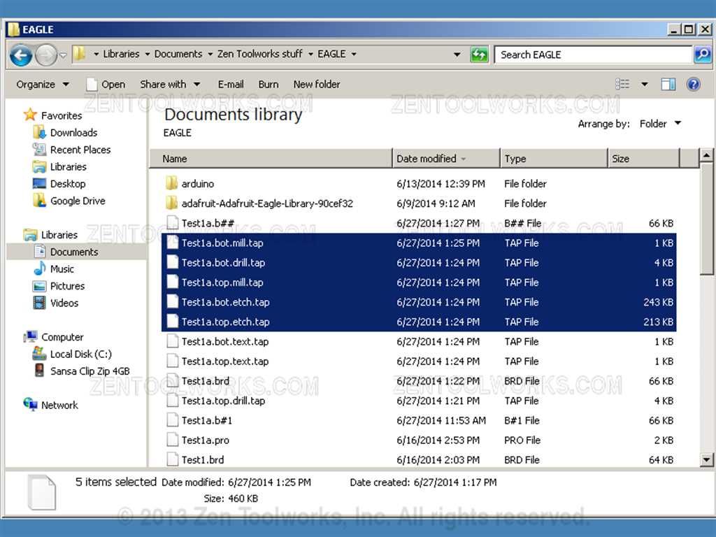
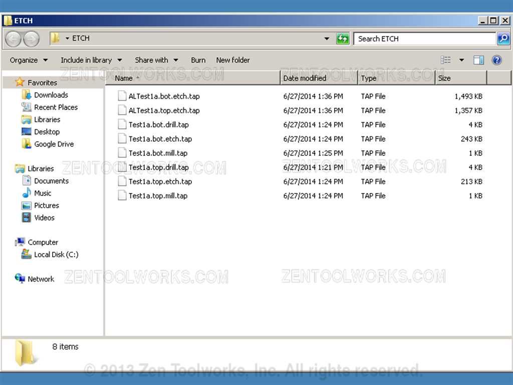
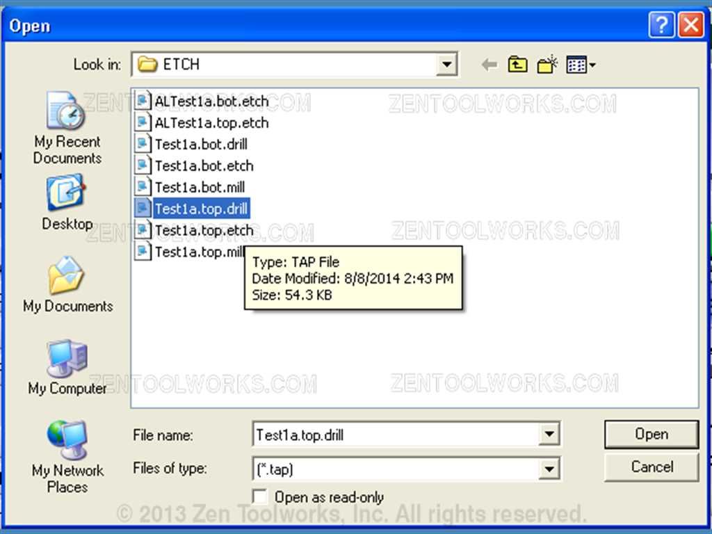
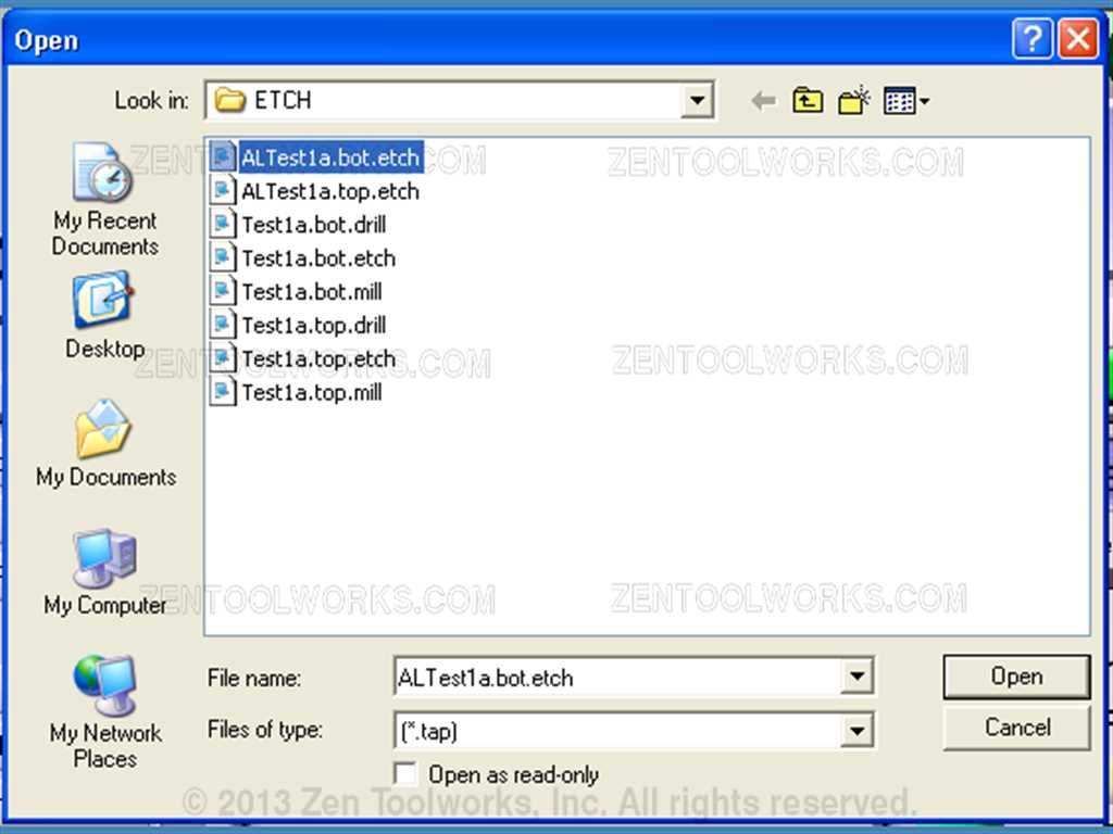
- Note that sometimes the program incorrectly displays the preview as a bunch of text.tap extensions. If this is the case then check the folder where you have your schematics if you see the files below in your folder then they were created correctly.
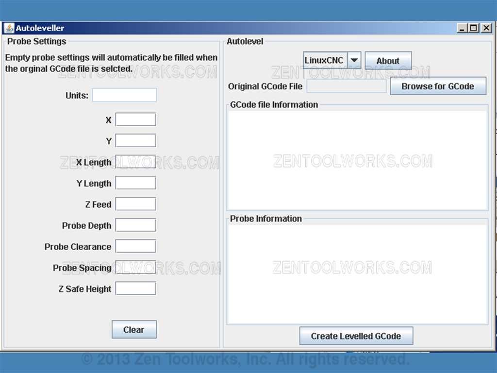
- Next we want to open up our Autoleveller. Once you do you will get a screen like this:
 ·
·
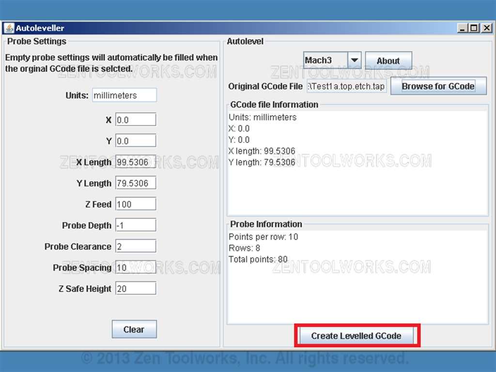
- First we press the down arrow on the dropdown menu and switch to Mach 3. · Then we click Browse for GCode and choose our top.etch.tap file.
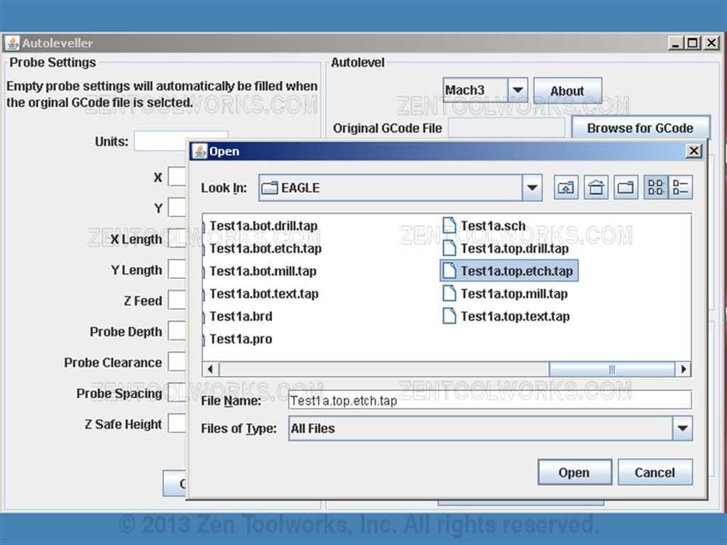
- Next we click open.
- Now that it is uploaded we click Create Levelled GCode.
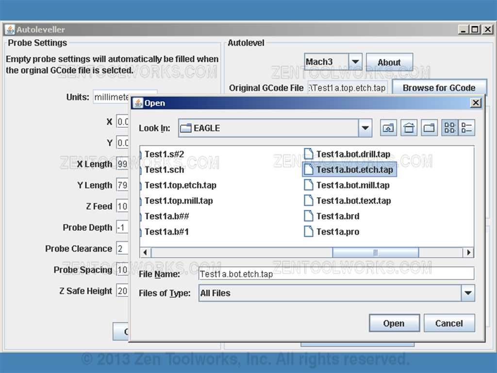
- We repeat the process with the .bot.etch.tap file.
 ·
·
- After you create the Autolevelled GCode for the .etch.tap files now we are ready to cut.
Step 7: Intermission to XP Machine
- Now for this part we need to put our created .tap files on a flash drive if we worked on them on a newer 64-bit windows operating system to place them on our more classic Windows XP or 32-bit Windows machine. · The files we need are our .etch.tap files, .drill.tap and .mill.tap both bot and top and our shiny new AL etch files.
Step 8: Mach 3 Setup
- First we need to get a computer with either Windows XP or a computer with the 32-Bit version of Windows Vista or 7. This computer also needs to have a serial printer cable port as to where we can hook up our Mach3 driver package. Currently the Mach3 software doesn’t support 64-Bit Windows software so we need an older computer to run it.
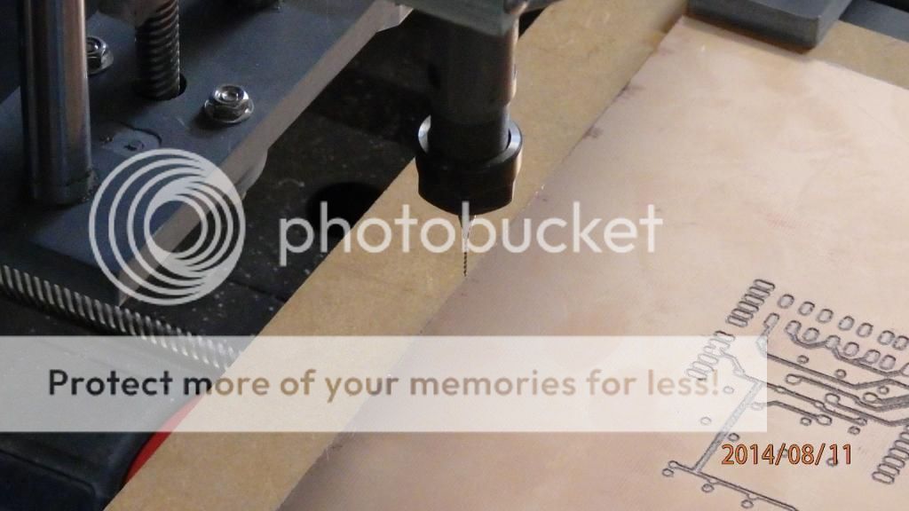
- Next we need to set up our CNC mill so that we can make our cuts and etches for our PCB.

- Pictured above is our ZEN Toolworks 7 x 12 CNC machine. We are going to be using this device for the remainder of our tutorial and we are going to be drawing specific references to it. Most of the steps that we are going to do can be used in other similar devices. Keep in mind that all CNC machines using the Mach 3 can be operated using the same concepts. Execution and mileage may vary however.
- First if it hasn't already been done, we are going to create a new profile for our machine. If this is already done you can just skip this part and move on to step 9.
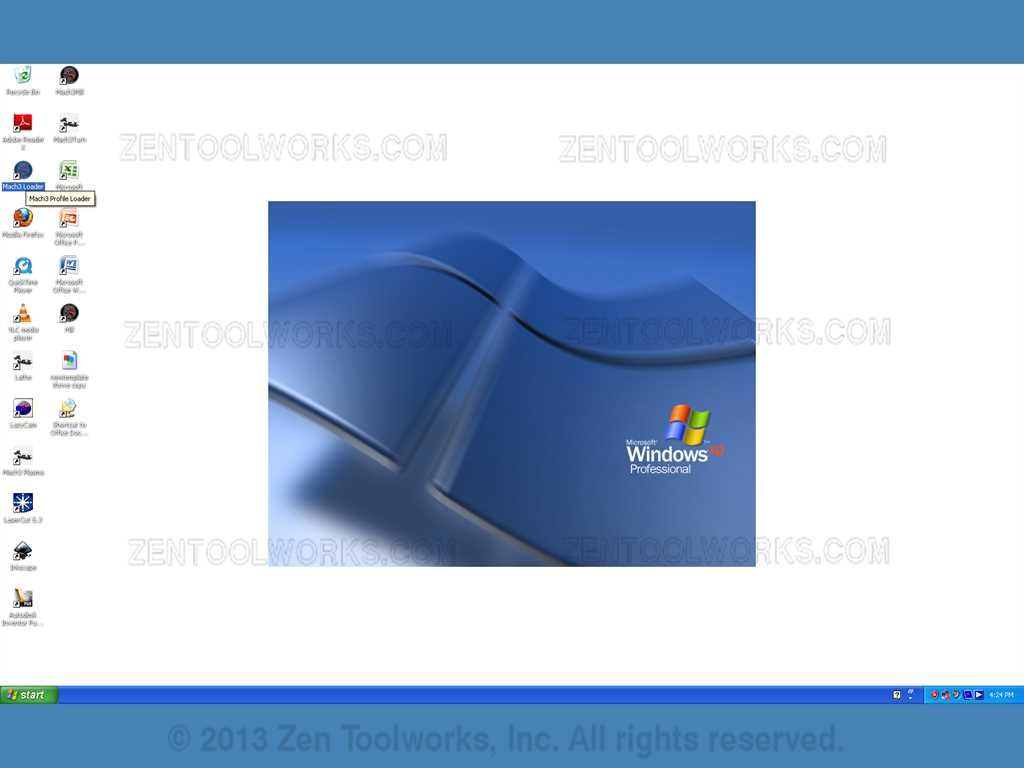
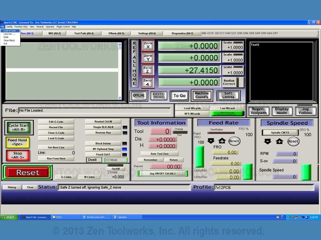
- We first go to the desktop and click on the Mach3Loader file.
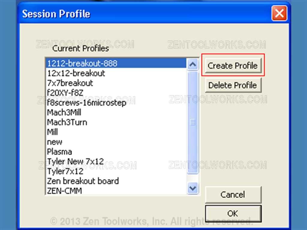
- Next we click on “Create New Profile”
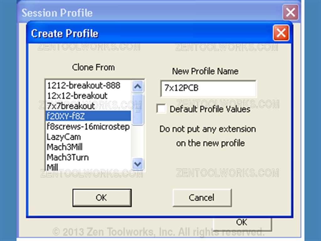
- We then name the profile and clone one that already exists; we can then later change the parameters to suit our needs.
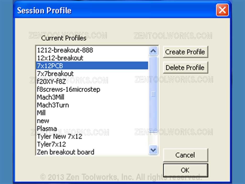
- After we have created our new profile we then go and select it and hit OK.
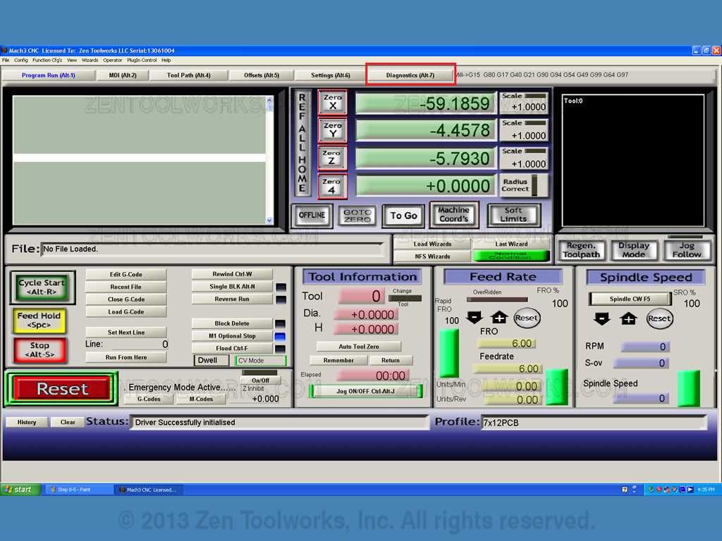
- And we should get our startup screen for our Mach3 program.

Step 9: Copper Board Setup
- Now that we have our Mach3 program started we can then probe the board using our Autolevelled PCB G-Code. First we must make sure that our machine is connected to our computer.
- Next we need to get our copper board.

- Now we need to secure the copper clad board to our CNC machine. There are many ways of doing this such as taping it down, using double sided tape or clamping it down. For this example I am using some double-sided tape to hold the board in place. Also worth noting that the board needs to be completely secure in order to get the best etch possible.
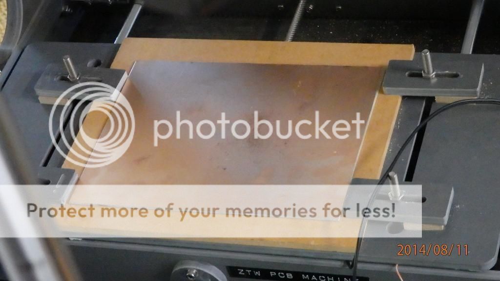
For this tutorial you will need to align the Copper board to something straight so that we can maintain a similar X and Y axis. For this tutorial I am using the clamps for holding down our wooden board to maintain straightness.

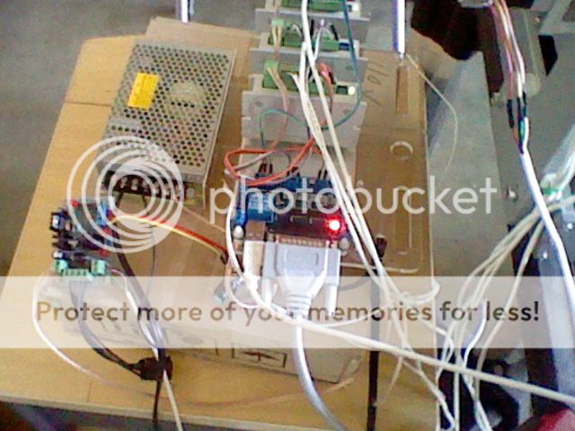
- Next we want to install two lead wires to the Mach3 controller package on our motor driver. We do this by getting two lengths of wire, inserting one into the Common ground and another into one of the other pins in the array.

- Next we then click on the Diagnostics tab on the Mach3 menu. We need this to test our probe wires.
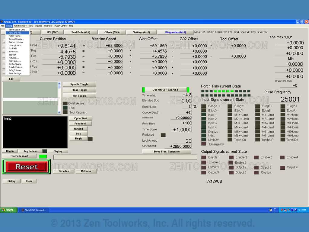
- Once we have entered the diagnostics tab we then go to Config > Ports and Pins.
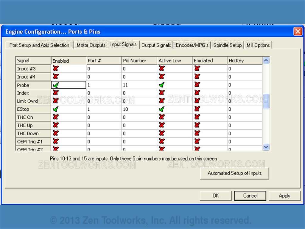
- On the next screen we click on the Input Settings tab.
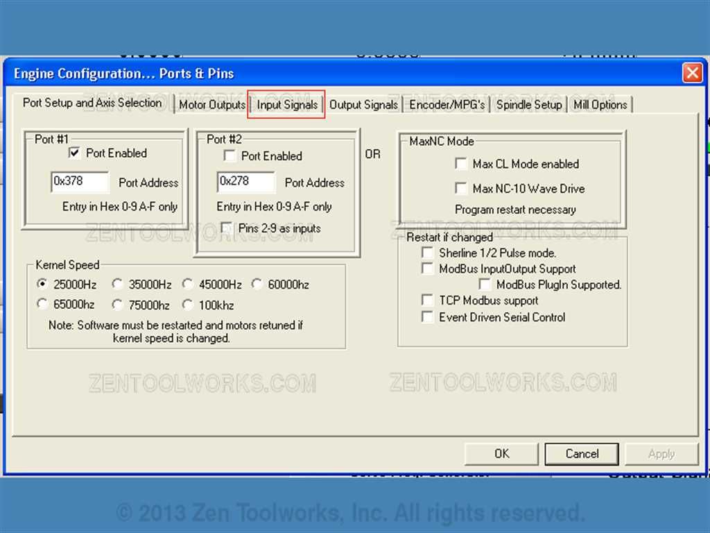
- On this tab we need to enable the Probe pin. We then need to define the pin as being in Port 1, a then we need to figure out which pin is the one that works for the port that we plugged our probe wires into. For my set up it is pin 11. We then enable the probe and enable it to be active low.
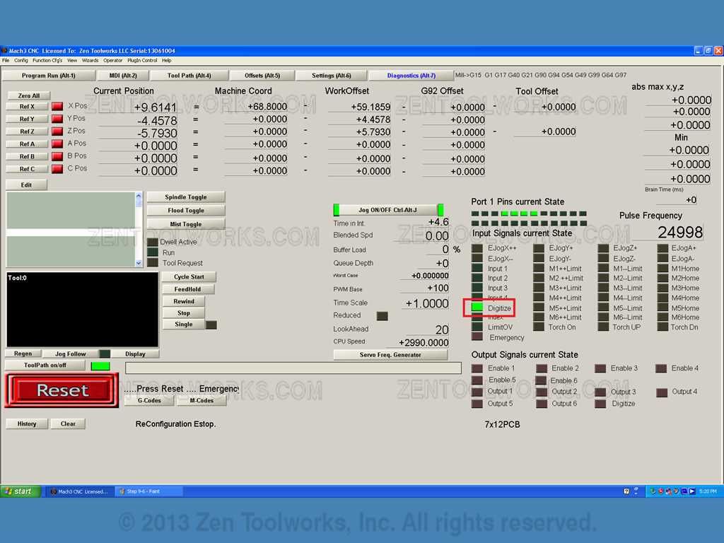
- Once we have our probe set, we then test it. We do this by going back to the Diagnostic screen after pressing Apply and OK. We then take both of our probe wires and touch them together.

- What we should see on the diagnostic screen when we touch the two wires together is the Digitize box light up. This will show that our probe is actually seen by the Mach3 software.
- Next we want to tape the wire placed in the GND pin to our copper board.

- We want to then hook up our other end to the bit we are using.

- Next what you want to do is press PgDn until your spindle barely touches the copper. What you are looking for is when you make contact with the copper the Digitize pin lights up on the diagnostics screen.

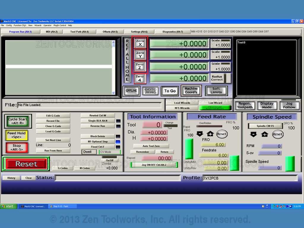
- When this happens you then press PgUp to lift the spindle off of the PCB board. You then want to find a nice area on the board where you want to make your etches. The autoleveller program starts at what is read as point (0,0) so you will want to choose a nice place to start etching and then Zero out the X, Y and Z axis. You do this by clicking Zero X, Zero Y and Zero Z.
Step 10: Probing the Board
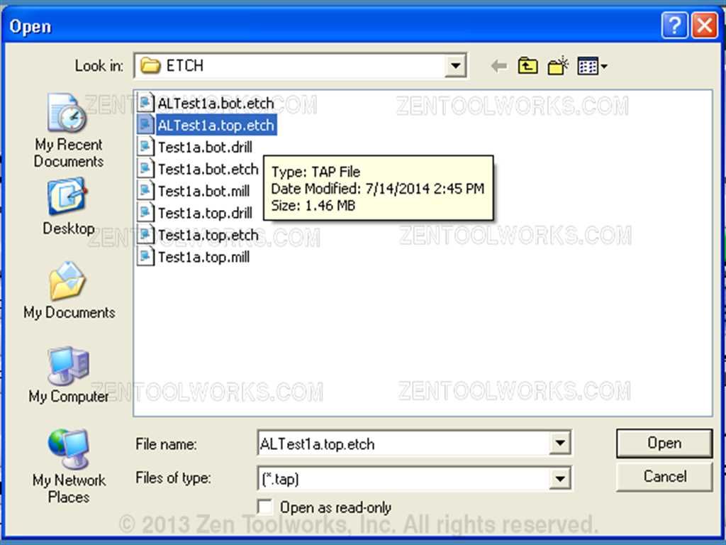
- Now the pre-probe setup is complete, we can then actually probe the board. Doing so at this point is super easy with the autolevelled program we made earlier. All we have to do is first load the program by going to File > Load GCode.
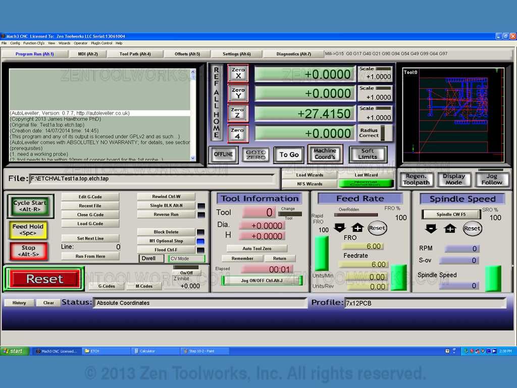
- Next we go and select our auto levelled file. The autolevelled file will begin with an AL in it’s name. In this case mine was AlTest1a.top.etch.
- The GCode will now be placed top-most left green window, you can scroll though the code if you wish.
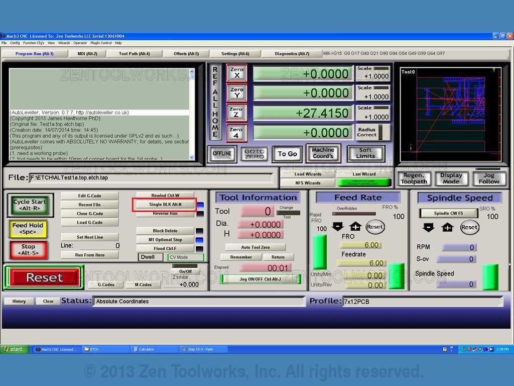
- Now that we have our GCode in place the first thing it is going to do is probe the surface of the board in several places. It will return the Z values into its later code to make a much better etch into the board. This allows us to have the most precise etches into the copper clad that we possibly can with the isolated traces that we need. · There are two ways you can let the Mach3 probe the board. One way is to click on Single BLK first the pressing cycle start only goes specifically step by step. This takes a while and may be tedious but it makes sure that all of the values for the Z axis are precise.
- The other method is to simply let the machine run its course. It will deliver the probed points with precision and becomes rather capable of etching the material.
- With either method you choose you will end up pressing the Cycle Start button which initializes the program. Keep in mind that you want to exercise safety at all times, wear eye protection as the CNC mill will fling about shards of copper and fiberglass as it is etching into the board. Also you want to make sure you are keeping an eye on it, so that you can press the emergency stop button when needed in case something happens and you need to cut power.
- Now just watch or continuously hit the Cycle Start button as the machine probes each point made by the Autoleveller software.

- Once it gets to the end of the probing part of the code the spindle will raise up and pause. With this now you have to take off the probe before you can start etching onto the piece of copper.

Step 11: Spindle Setup
- · For this step we have to first make sure that our spindle is wired up correctly using our Pulse Width Modulator or PWM for short. This device allows us to manually control the speed of our spindle package as well as acting as an emergency stop. You can also control the speed from the Mach3 interface or the GCode itself as well. · The way you would wire up the spindle package is shown here:
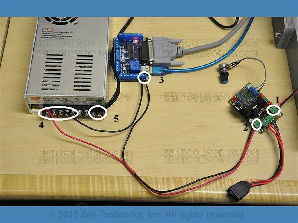
- PWM to Spindle
- PWM to Power Supply
- Negative from Power Supply to the internal relay of the Mach3 motor driver, then to the negative port of the PWM.
- Positive from PWM to Positive voltage on the Power Supply 5. 120v DC to Power Supply.
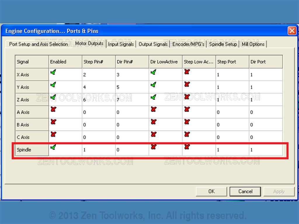
- Once you have your spindle package set up like above you can then go towards setting the spindle up in the Mach3 software. You do this by going to Config>Ports and Pins, then you want to click on the Motor Outputs Tab.
- Next you want to make sure that the Spindle is enabled. You do this by setting the ports to be 1 and you want to then enable it.
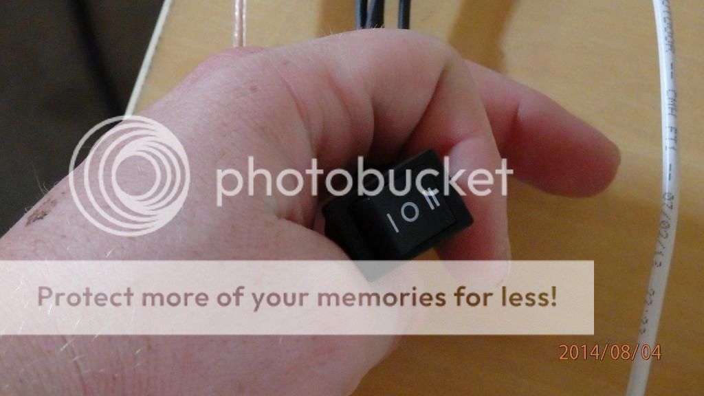
- Now you go to the PWM and make sure that the switch is turned on.
- Now that our spindle switch is turned on, you will notice that the spindle motor isn’t running. You can start up the motor to check your connection by clicking the “Spindle CW” button. This will turn on the spindle from the Mach3 software
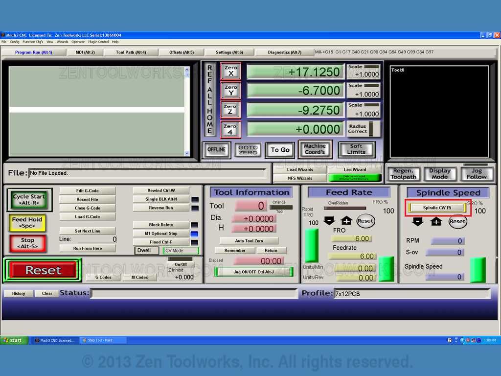
- Now that we know that our spindle works we then can start our etching.
Step 12: Etching Our Board Part 1
- Before you start up the program again for the 2nd part of the etching process, you want to make sure that you have some kind of eye protection as the machine will be grinding out bits of copper and fiberglass.
- You want to also keep an eye on the machine just in case something goes wrong such as, a bit crashing or the board not cutting properly. You want to be there to hit the emergency stop switch.
- Once everything is cleared and you are ready wearing your eye protection you can hit the “Cycle Start” button to get the etching started.

Step 13: Drilling Our Board
- Now that our surface etching is done we can move on to drilling. Please note that there is no specific order for neither the etching nor the drilling, if all measurements are done correctly you should have a great looking finished product. This may take a lot of trial and error if this is your first time etching out a PCB or even using a CNC machine such as the ZEN Toolworks 7 x 12 we are using for this tutorial.
- First we need to change our bit to the drill. Be careful when dismounting the endmill because dropping the bit will probably break it.
- Next load your .top.drill.tap file.
- Hit the “Cycle Start” button and watch the machine drill the holes.

- One thing you need to be sure of is to mind the fiberglass. Keep the board free from debris and DO NOT BREATHE IN THE FIBERGLASS! This may cause permanent damage to your lungs.
- Once the drill code is done clean up the board with a shop vac.
Step 14: Etching Our Board Part 2: Board Flip
- Now that our board is drilled out we can leave the drill bit in for one last thing. We need to make a hole at the X: 0 and Y: 0 mark. You can do this by clicking the spindle start button and slowly hitting the PgDwn key to create a small hole though the board. We are going to use this for the X: 0 and Y: 0 portion of the other side. As the autolevelled .bot.etch.tap file is mirrored along the X axis.

- Once you have your hole you can then flip the copper cladding to expose the back side of your board. Make sure to butt it up against the straight edge that you made so that the holes line up. You have to replace your probe if you are going to be using the autolevelled GCode before you continue. Note where you drilled out at X: 0 and Y: 0. You need to move your gantry to that point on the board. Once you do Zero the X and Y axis.

- You then manually move the gantry using the arrow keys to the newly drilled hole. Once you do you then want to align it up perfectly with the drilled hole. Once you have confirmed that the hole is lined up with your end mill you then click “Zero X” and “Zero Y” to snap that coordinate to being X:0 and Y:0.

- Be sure that your bit is changed back to the end mill before you start the probe.
- Now open up your .bot.etch.tap file and run the probe.
- Remove the probe and begin etching out the bottom of the board.

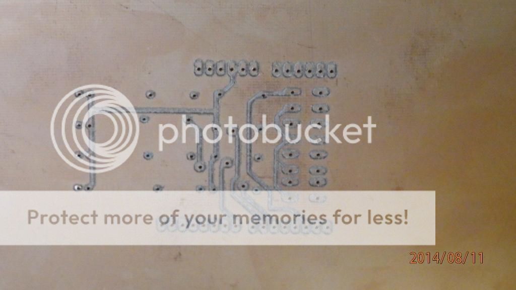
- Once the process is complete you can now step back and admire your work. You can then overlook all of the traces and make sure that there are no shorts.

Step 15: Finishing Up!
Step 15:
- Now that both sides of the board are complete you can sand down the copper a bit to clean up the traces. Use a super fine piece of sand paper to do so.

- All that is left to do is cut it out and solder your components and it is ready to go.


