Introduction: Making a Rope Pump for a Borehole.


The best and cheapest option for getting water out of a borehole seems to be the rope pump.
It consists of a rope with rubber disks riding up a pvc conduit, at spaced intervals usually determined by the depth of the water table in the borehole, a hand driven pulley above ground and a guide foot at the bottom.
A bucket bailer is the cheapest, consisting of a length of pvc pipe with a check valve in the bottom and a length of rope, but it tends to become rather tedious after frequent use.
Step 1: Rope and Rubber Disks.


I started with attaching rubber disks to the rope, my borehole is 4m deep with a 50cm depth of water table which dictated the inter disk spacing to be 50cm on a 11m length of polypropylene rope.
I used 21 rubber door stoppers with a 21.5mm dia on a 5mm dia rope, riding inside a 25mm pvc conduit.
I inserted short sections of the rope and melted the ends, the stopper was then slid over the still hot plastic.
This needs to be done both in front of the stopper as well as behind it.
Step 2: The Guide Foot.


This is a combination of 25mm electrical pvc conduit with 90 degree irrigation bends for the frame, a 50mm dia piece for the foot inlet and a 50mm end cap to create the transition to the 25mm pvc running to the surface.
Step 3: The Drive Pulley.


I cut out both tyre beads off a 175/65 X14 tyre to form the pulley flanges.
The best way to do this is to use the serrated blade of a Leatherman tool.
A jigsaw is pretty much useless and a cutoff blade in an angle grinder makes a very sticky rubber mess and is not advised at all.
Using a circular saw is dangerous as the rubber will grab the blade... DONT DO IT.
Rebar was used for the spokes, welded to the hub, half pieces of a 25mm steel tube served as flanges for the tyre beads to seat into.
A 8mm stainless steel shaft with flats ground helps to lock the drive handle and pulley in place.
The handle is welded 16mm steel tube with a 25mm dia pvc tube that is a slip fit.
Step 4: The Frame.

This is a simple A frame formed out of the tubing that I used after I had dug the borehole with a hand auger.
The base sections are 16mm dia, bent in a vise and the top sections are 25mm dia for a slip fit.
The only welding in this step is the top steel pieces that house the 608 bearings.
My hydraulic press from a previous Instructable (10 ton press) was used for the 90 degree bends and the flattened ends of the frame braces.
Step 5: Test Fitting.


Once the frame is finished, it can be fitted over the borehole pipe (110mm UG pipe) to determine the bends for the slack side of the rope down feed pipe, the height of the borehole pipe and the height of the 25mm conduit feed pipe.
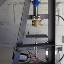
Step 6: Final Assembly and the Outlet.


Once the bends have been made with the heat gun, the slack down pipe can be fitted as well as the feed pipe from below.
It is advised to fit a larger transition above the water outlet which stops the water from travelling up higher and spilling over the top of the feed pipe. I used 40mm dia pipe and T piece which works well.