

Introduction: Motion Sensing Digital Camera & Alarm (a.k.a. the Critter Cam)


Welcome to my instructable on how to make an Arduino-controlled motion sensing camera and alarm!
The motivation behind this project, which I worked on in my electronics class at Pomona College, was the need to keep away varmints (particularly raccoons) that were digging up my parents' yard. Although a simple motion sensing alarm would probably do the trick, I decided to add a camera to the circuit so that I could actually capture the critters in action! I have yet to field test the device, but the results so far are promising.
One really great thing about this project is that it builds upon the work of several other cool instructables:
· Hacking A Keychain Digital Camera for Arduino Control by smb
https://www.instructables.com/id/Hacking-A-Keychai...
· Cat Repelling PIR motion sensor (covert) speaker box alarm by briannaw
https://www.instructables.com/id/Cat-Repelling-PIR...
· PIR Alarm Motion Sensor (with Encasing) by chuck4747
https://www.instructables.com/id/PIR-Alarm-Arduino...
So without further ado, let's build it!
Step 1: Supplies and Tools


1) An Arduino uno (http://arduino.cc/en/Main/arduinoBoardUno)
2) Arduino software (http://arduino.cc/en/Main/Software)
3) standard usb cable for your Arduino to communicate with the software
4) A 9V battery with an adapter (http://playground.arduino.cc/Learning/9VBatteryAdapter)
5) Digital Concepts “Key Chain” digital camera (costs about $5.50). Can order them from Amazon at http://www.amazon.com/Digital-Concepts-Key-Chain-...
o IMPORTANT: you will need the software installation disk that comes with the camera so that you can install PhoTags express, which allows you to upload your images to a PC (note that you must have Windows 2000/MEXP/Vista 32-bit).
6) Passive infrared sensor (PIR). There are a variety of sensors out there so feel free to choose the one that suits you. For your convenience, I have listed two common models that are compatible with this instructable:
o Here is a datasheet for a sensor very similar to the one I used. The output prong is located between the positive and negative/ground, just like the sensor I used. https://www.futurlec.com/PIR_Module.shtml
o Another model can be found at Sparkfun (https://www.sparkfun.com/products/8630). Note that the negative/ground prong for this model is in between the positive and output (called “alarm” in the datasheet).
7) A super bright white LED. I used http://www.mpja.com/8mm-Super-Bright-White-100000... but there are plenty to be found on Sparkfun as well.
8) One other LED of your choosing. I used this to trouble-shoot my prototype and did not include it in my finished product.
9) A small piezo buzzer (https://www.sparkfun.com/products/7950)
10) One AA battery (1.5V) and battery holder. I strongly recommend a single battery holder. You can order one from Mouser Electronics (here are the results for a search I performed: http://www.mouser.com/Power/Battery-Holders-Clips-...
o If you use a multi-battery holder instead, make sure that you can easily solder an extra wire or two to one of the sockets (Step 4 shows exactly what you need to solder). Battery holders with external solder tabs are ideal.
11) Two relays. I used 8-pin dual in-line package (DIP) relays. A really great example is provided here: http://www.alliedelec.com/search/productdetail.as...
o the configuration of the relay will depend on the model, so be sure to reference your relay’s data sheet to understand how it should be wired up. If you don’t know how relays work, I highly recommend you check out this instructable: https://www.instructables.com/id/How-Electronic-Sw...
o If you’re stuck without a datasheet (like I was), there is a simple way to determine how to hook your relays up (which is explained later in this instructable).
12) two DIP 14-pin or 16-pin sockets (https://www.sparkfun.com/products/7939). I used 16 pin sockets but you’ll only need 14 for your 8-pin DIP relays.
13) One 56 ohm resistor (for use with the 8mm super bright white LED; be sure to check your LED’s typical/continuous forward current and forward voltage so you can calculate the ideal resistance for yourself!)
14) One 10K pull-up resistor (for your PIR sensor)
15) At least 4 arduino stack-able header pins (https://www.sparkfun.com/products/7937) . You’ll need two 6 pin and two 8 pin sockets. I say at least because if you make a mistake during the final soldering process, you'll need backups.
16) 1-2 additional stack-able header pins for your PIR sensor, to place your sensor on your circuit board. These are not required if wires are already attached to the input-ground-output prongs (such as https://www.sparkfun.com/products/8630).
17) Proto-board (for finished product)
18) Optional, but incredibly helpful: breadboard for testing out your circuit before soldering
19) Jumper wire kit (https://www.sparkfun.com/products/124)
20) A few feet of insulated wire, ideally in several colors
21) Wire connectors (you may need them if your battery holder does not have solder tabs; see Step 4 for details)
22) Plastic ties to keep soldered wires in place
23) Optional: electrical tape in several colors (depends on how many colors of insulated wire you have)
Tools
· tiny Philips-head and flat-head screw drivers
· wire cutter and wire strippers
· two multimeters
· soldering iron and solder
· solder stand (makes life much easier if you don’t have an extra pair of hands to help you)
Step 2: Taking Apart the Keychain Digital Camera

This step is based on step 2 of smb’s instructable at
https://www.instructables.com/id/Hacking-A-Keychain...
I took most of my pictures after throwing away the parts I didn’t need, so while the pictures above are helpful (especially once you’re looking at the camera’s circuit board), I recommend you check out smb’s photographed instructions to fill in the gaps as you dissect your camera.
First, you will need to open up the battery compartment at the bottom of the camera to remove the AAA battery (it should be in there if your camera is new). Once the battery has been removed, you’ll need to use a flat-headed screwdriver to pry open the front cover of the camera (as demonstrated in the aforementioned instructable). Like the author of that instructable, I found it easiest to dig under the bottom-right portion first. The cover is a bit stubborn, but with a little persistence you’ll get it open in no time.
Once the cover is open, you will see a screw near the bottom, below the LCD display. Use your Philips screwdriver to unscrew it. Once you have done this, return to the camera’s battery compartment to remove the tape (you may have to scratch away some of it with one of your screwdrivers). Once the tape is removed, you will be able to open both halves of the camera (which the screw and tape had been holding together).
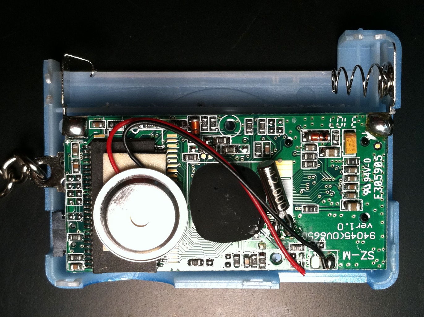
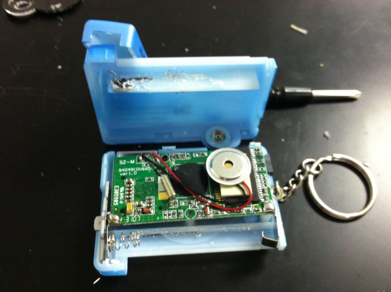
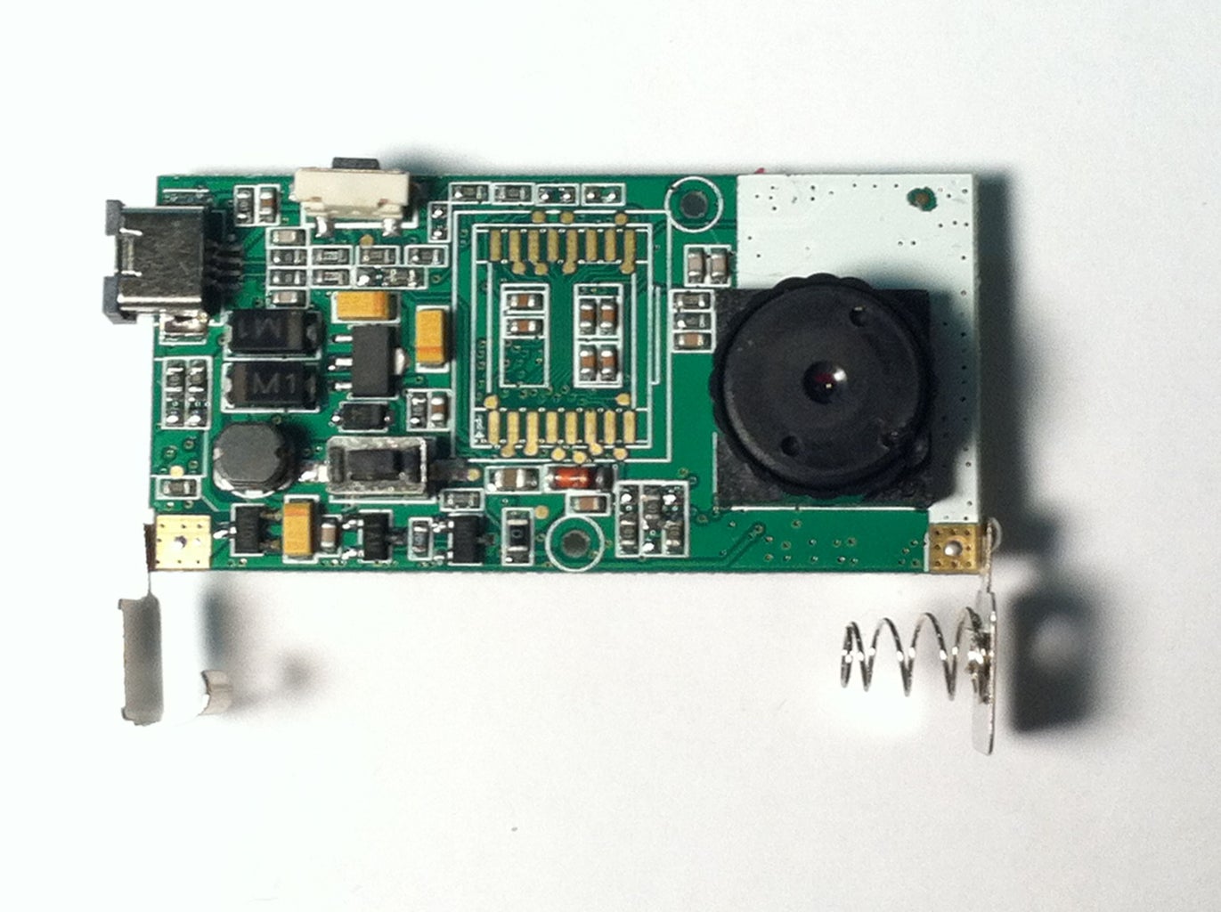
My first picture demonstrates what both halves of the camera should look like with all the components attached, minus a screw or too (Unlike the camera in smb’s instructable, my camera only needed one screw since its positive battery holder was soldered). Unscrew the remaining screw from the top left/center part of the circuit board (see fourth image), and from the positive battery compartment if present.
With all the screws removed, you should be able to remove your circuit board from the camera frame. Don’t panic if some pieces fall out! The "on" button, shutter button, viewfinder and LCD display will probably come off. This is perfectly fine because you won’t be using any of them again. One other piece that may become detached is the circular metal piece (labeled in the first image). Although it will not fall off (it is wired into the circuit board), it may detach from the foam tape. If this happens, you may want to apply a fresh layer of double-sided tape to secure the piece. This circular piece seems to generate the “beep” that you hear whenever you press the power button or shutter, because once the piece became detached, my camera stopped beeping, even after I reattached the piece with new foam tape. The beep is certainly not necessary, but you don't want a loose piece getting in your way, especially since you will need to solder some wires to the circuit board.
Two other pieces that may break away from repeated handling are the positive and negative ends of the batter holder. If you plan on keeping the camera frame in your final product, you’ll need these pieces and will have to solder them back on if they fall off. However, if you choose to abandon the frame (as I did), you will have to remove the positive and negative ends of the camera holder, so if they fall out, you’re ahead of the game!
Step 3: Soldering Prep


This step can be tricky, especially if you have not soldered before (there are some good soldering instructables out there if you are new to soldering). The reason for this is that the four connections that you will be soldering to are fairly small and close to other conducting parts of the circuit. Thus, to prevent short-circuiting your camera, you will need to be extra careful not to let the solder leak into other conducting parts of the circuit board. On the bright side, there are only four connections you need to solder, so if you’re nervous, just take a deep breath. Now, let’s get to it!
It may take a while for your soldering iron to warm up, so go ahead and turn it on before reading further.
Now, ask yourself whether or not you’d like to keep your camera frame. You certainly don’t need it, and will not be seeing it again in this instructable. However, if you do choose to use the frame, you will need to follow steps 3 and 4 of https://www.instructables.com/id/Hacking-A-Keychain-Digital-Camera-for-Arduino-Cont/ , because the frame limits where you can place your wires. On the other hand, keeping the frame will save you the trouble of adding a battery holder, though you will need to use a AAA. However, I personally found attaching the AA holder to the camera much easier than fitting everything inside of the frame, and because the flimsy lcd display broke after opening the camera, I found the frame to be useless anyway.
Before you do any actual soldering, test the buttons with a multimeter to see how they behave (see the first two images). You should observe resistances in the mega-ohm range when the buttons are not pressed (i.e. the circuit is open), and no resistance when the buttons are pressed (the circuit is closed). If this does not happen, you are probably not touching the correct connectors. By recording how the circuit behaves now, you can troubleshoot if you encounter any problems down the line.
Time to prepare the circuit border for soldering. You will be attaching two wires to the ends of the shutter button, and two more wires to the ends of the power button (both of which I have labeled in the third image). Doing this will allow the Arduino to digitally “press” and “release” the buttons. Gather a foot each of the four wires, and a fifth wire to connect to ground. You’ll need to strip both ends of these wires. The end that you solder to your board should be only 1-2 mm thick (unlike what I've shown in the fourth picture); if it’s too long, you risk touching the bare wire to other parts of the circuit.
I won't be getting to the ground wire until Step 6, so don't lose it.
Step 4: Soldering the Switch-Controlling Wires to the Camera Board


Now secure your board to your soldering stand (as shown in the image), or else ask a friend for help. If you want to be extra careful, you can place a wad of paper around the part of the circuit that you clamp down. Next, secure your first wire to another clamp (or your friend’s other hand). By now, your soldering iron should be hot enough to melt solder, so pick up a good length of solder with one hand and the iron (carefully!) with the other, touch the tip of the solder to a connector and wire, and then touch your iron to the connector and wire so that the solder melts onto them and not the iron. Repeat this process for the other three connectors. If you are having trouble, check out a soldering instructable. When you think you’re done, check the second and third images for comparison.
The next step is optional if you have a single battery holder. Step 6 is where you’ll connect the battery holder (and ground wire) to your camera circuit board.
Step 5: Optional If You Have a Single Battery Holder


If you have a holder for multiple batteries (like I did), you’ll need to attach positive and negative wires to a single socket (or even better, use the socket with the positive wire directly attached). The battery holder I used had a steel wire that connected the negative end of the first socket (bottom socket in the images) to the positive end of the third socket (top socket). I cut off the wire from the third socket and soldered a black wire to the remaining steel (see fourth image). Because solder does not stick to steel very well, I used a wire connector to hold everything in place. If your battery holder does not have an external wire connecting the sockets together, check for solder tabs (pieces of metal on the outside of the socket that solder sticks well too). My holder did not have solder tabs, but if yours does, then soldering should be fairly painless.
If you don’t have external connecting wires or solder tabs on your battery holder, you might try soldering a wire to the negative coil of the battery socket. However, this is a very difficult task (one that I attempted unsuccessfully, in fact). If you’re a solder wiz, then go for it! Otherwise, buy a single battery holder or one with solder tabs.
Step 6: Connect Your Battery Holder to the Camera Connector

Now you will be soldering the positive and negative wires of your battery holder to the positive and negative ends, respectively, of your camera connector. You will be soldering these wires to the back side of the circuit board (see image). If the original positive and negative ends of the camera’s battery holder are still connected, break them off or melt the solder off. Then apply your solder and wires to their respective corners of the circuit board. This process is exactly the same as the soldering process in Step 4, but easier because you have more space to apply solder.
Before we move on, we need to solder that ground wire I mentioned earlier. Solder this wire in the same corner where you soldered the black negative battery holder wire. Make sure that both wires are secure before moving on.
Step 7: Building Your Proto-Circuit


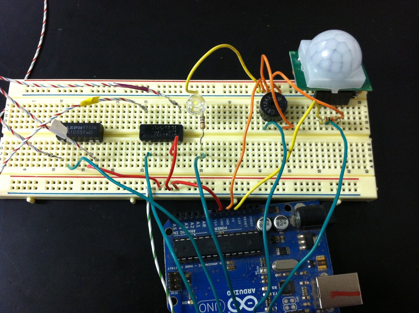
Now for the fun part! The annotated breadboard and schematic diagrams will help you understand how everything fits together (note that the annotation for the schematic diagram is concentrated in the left portion of the image). I’ve also included a photograph of my actual assembly for comparison. In the breadboard and schematic diagrams, you’ll notice that green wires connect components to the digital inputs of the Arduino, red wires connect components to a positive voltage source, and black wires go to ground. The blue, white, yellow and purple wires that connect the camera switches to the two 8-pin DIP relays represent those same wires in the actual photograph (where the colors correspond to the colored electrical tape on each wire). The three wires on the PIR sensor illustrate the 5V (red), output (yellow), and ground (black) ordering of the pins on the PIR model I used. Note that unlike the diagram, I needed a stack-able header pin to attach my PIR to the breadboard.
If you need to figure out how to hook up your relays and don't have a datasheet on hand, use the "beep" function of your multimeter (which "beeps" when your probe wires touch electrically connected parts of a circuit). A relay is a switch that contains both open and closed circuits simultaneously. When no voltage is applied across the relay's magnetic coil, closed circuits are called "normally closed" and open circuits "normally open". When voltage is applied, however, the coil will pull the internal switch towards it, switching "normally closed" circuits to open and vice-versa.
For this circuit, we want the 5V signals from the digital pins of the Arduino to electronically "press" the camera's buttons by closing the switch between them. Put another way, the camera switches are "normally open," and only close when a voltage is applied across them (or when a finger presses them). Therefore, we need to apply a voltage across a "normally open" connection of the relay so that this connection closes when power is applied. As shown in my schematic diagram, both buttons are connected across two pins that make up a "normally open" circuit.
So, how do you use a multimeter to determine the location of "normally open" pairs of pins? The easiest approach requires an intuition of how 8-pin DIP relays are configured. After looking through scores of datasheets, I noticed that the magnetic coil was usually placed across pins 2 and 6 (the inner bottom pins on a schematic diagram). Each of your relays should have a small circle on one end of the top face that identifies the "left edge" of the relay on a schematic diagram. The bottom left pin is numbered 1, the one to its right 2, and so on, going counter-clockwise around the body of the relay until pin 16 is reached at the top left.
Anyway, I based on my research, I assumed that the positive voltage needed to be applied to pin 2, and the ground connected to 6. After applying 5V across these two pins, I used the beep function of my multimeter to see which pairs of pins were connected (and caused the meter to beep). For both relays, I found three pins that were connected when 5V was applied across 2 and 6, so for each relay I chose the "normally open" pair that was the most symmetric.
Once you've connected everything together and have understood the behavior of your relays, you are ready to code!
Step 8: Programming Your Proto-Circuit
Download the attached program and save it to your Arduino software (if you haven't already, you'll need to download it from Arduino's website). I've thoroughly annotated the code, so troubleshooting should not be difficult (but do let me know if you encounter any problems). I have attached both a text file and pdf. Keep in mind that you may have to fix some lines due to formatting changes between my original file and the text file. For instance, there may be comments that spilled over into the next line, where they are no longer commented-out of the main body of code.
This program tells the camera to take pictures whenever motion is detected. Once the camera has taken a picture, the white led will flash and the buzzer will sound. The white LED will also turn on as the picture is being taken. The test LED will flash whenever the power or shutter buttons of the camera have been pressed.
Initially, 15 seconds are set aside to calibrate the PIR. Aftewards, the program is divided into two routines, one that runs when motion is detected by the PIR, and the other when no motion has been detected. Each of these routines is further subdivided into two routines. For the "motion-was-detected" routine, one subroutine runs if the camera was off during detection, and the other runs if the camera is already on. For the "no-motion-detected" routine, one subroutine runs if the motion had just stopped, and the other runs if no motion has been detected for a while.
Has your camera stopped beeping when you press the power- and shutter-buttons manually (with the battery attached, of course)? If so, then purpose of the subroutines is to monitor the camera's activity. With these subroutines, the code prevents the Arduino from pressing the power button more than once while the camera is on. If that button were pressed multiple times while the camera was on, the camera would transition from the normal photography mode into an image management or video mode. Since it would be very difficult to write a program that keeps track of these various modes (which are entirely unnecessary for our device to function), I wrote the code to prevent the Arduino from ever activating one of these other modes.
This code also takes advantage of the fact that after 30 seconds of inactivity, the camera falls asleep.
Once you have the code and circuit ready, plug in your Arduino to your computer's usb port to test the program. As soon as you've finished uploading the program to the Arduino, click the "Serial Monitor" button at the top right (it has a magnifying glass with a dot in the middle) so that you can monitor the Arduino's progress. Check out the next step to see an example video, and how you can use your multimeters to monitor your camera.


Step 9: Testing Your Proto-Circuit
The above video is a demonstration of how you can test your proto-circuit (no sound on this one, unfortunately. For a video with sound, see the finished product in the final step!). I've annotated the video to guide you along. The voltmeter in the video is wired in parallel with the two ends of the power button. When the button is unpressed, the voltage across it is either 1.863 V (power is on) or 3.215 V (power is off). For the brief moments that the button is pressed, the voltage goes to 0 V. You can apply this procedure to the shutter button to measure its voltage when the camera is on and off. I found the two "unpressed" voltages for the shutter to be 0.159 V (power off) and 3.258 V (power on). You'll probably get slightly different values for the voltages across the power button and shutter of your camera, so be sure to record them for your own reference!
Step 10: Time to Assemble the Real Thing!


If your proto-circuit is functioning like the one in my video, then it's time to make the real thing! You will need a proto-board to solder your components and wires onto, and a wire cutter to trim the wires, including those on your LED and resistors. If you haven't already, turn on your soldering iron to warm it up.
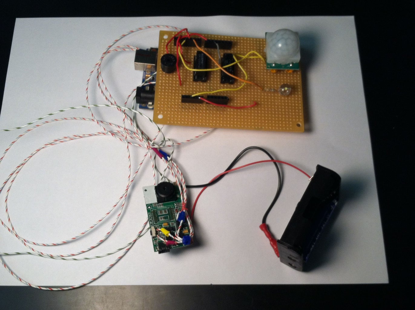
I have attached some pictures of what my final circuit looks like. Feel free to organize the components however you like, just as long as you keep track of where everything connects (definitely refer to the schematic diagram, which I've re-posted in this step).
Here are some things to keep in mind:
*The Arduino board attaches to the bottom of the two rows of header pins. One row consists of two 8-pin pieces, and the other row has two 6-pin pieces. The 8-pin pieces attach to the digital pins (numbered 0-13 and including ground), and the 6-pin pieces attach to the analog inputs, 5V and the other two ground pins. You will need to leave one hole open between the two pieces for each row (to match the space between the two sets of pins for each row of the Arduino).
*That said, DO NOT TRIM your header pins! Otherwise, they won't fit inside your underlying Arduino! I made this mistake because I had not fully planned out my circuit board and got carried away with trimming. Let me tell you, unsoldering those pins was a big pain! Even worse, I removed the copper on all of the holes that I unsoldered, which meant that I had to find new rows of holes to solder the replacement pins to. And I obviously had to find a fresh set of pins. So, don't be careless like I was: keep those header pins nice and tall!
*Solder the header pins first, and space them so that the Arduino will fit directly under them. Once you've soldered these pins, you can move on to the other components. As long as the wires of these other components are trimmed, you can place them directly over the Arduino. You can (and should) remove the Arduino when soldering these components.
*I did all of my soldering on the bottom of the board (where the copper was located) and placed my components on the top side. I recommend you do the same. Life will be much easier if you tape the component to the board while you solder the pins/wires to the bottom. Tape is necessary to keep your header pins perfectly straight, because if they are not perfectly straight, then you cannot insert your Arduino into them.
*The luxury of having header pins is that you can stick the ends of some wires into them, so if you fry one digital pin, you can move the wire to another and redefine the pin in the code. However, remember that the other end of the wire will still need to be soldered to the component it is connecting.
*If you are using 16 pin sockets (as opposed to 14) for your two relays, keep track of where your relay pins are attached. Having that extra pin in each row of the sockets can be very confusing.
With all these tips in mind, go ahead and solder away! When you're done, give yourself a pat on the back, then go on to the final step.
Step 11: The Finished Product
Now it's time to test your newly assembled circuit. Run the code as before and see which components work and which don't. If some components aren't working, check the connections for those components. If you have to unsolder a few wires, it's no big deal. If you tend to apply fairly large amounts of solder, check your connections with an ohm-meter to see if you have introduced any short-circuits. If so, you will need to remove that excess solder until the short circuit is removed.
Check out the video above for reference. If your circuit works just as well as mine did, then congrats!!! As you may have guessed, installation of the PhoTags Express software is necessary for you to view and save your photos.
At this point you can replace the usb cable with a 9V battery and adapter (if you haven't already, check out the instructable at http://playground.arduino.cc/Learning/9VBatteryAdapter). With the battery, you can place and operate the device anytime, anywhere (but make sure you upload your photos frequently; the camera can only store about 20 photos at a time. Moreover, the camera loses its memory after the battery dies or is removed. The camera drains the battery fairly quickly, so it would be a shame if you lost some valuable reconnaissance footage to a dead battery.
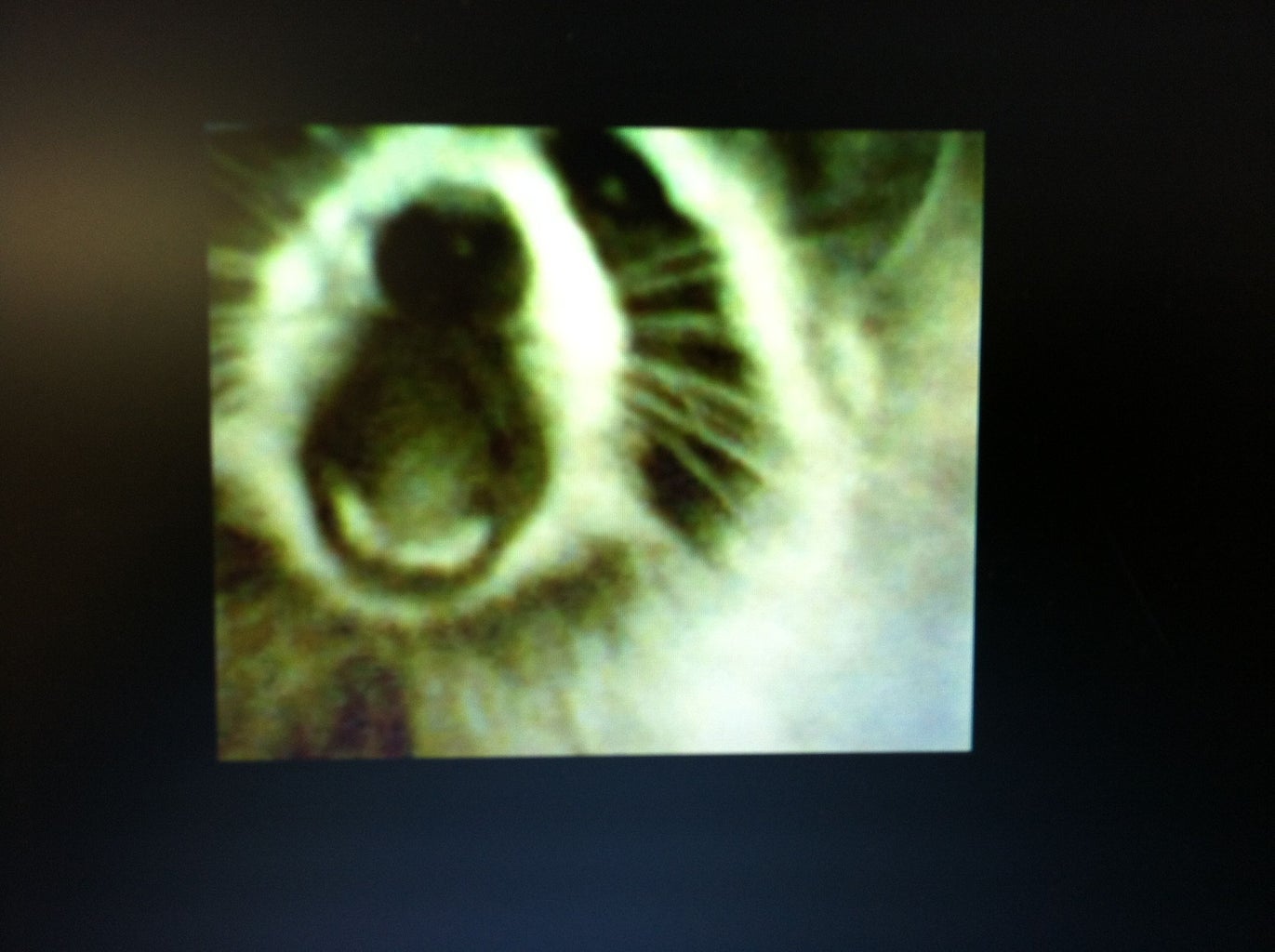
My little cardboard box won't survive an animal encounter for very long, so I plan to construct something sturdy enough to withstand curious (or even aggressive) nudges from a cat or raccoon. I will also need to test the sensitivity of the device (to determine whether a leaf, for example, would set it off). I am also aware that the camera has different resolution settings that affect how much memory can be stored, so I might tinker with that too to see if I can save more photos at a time. Finally, I will need to position the camera in such a way that it can get a clean shot of the target (rather than half a snout like my video demonstrated).
The best thing about this device, however, is that it has a wide variety of potential applications. It can serve as a doorbell for your dorm room, or it can be used as a security camera (if you suspect your roommate/suitemate is stealing food from your fridge). One application that I would readily put to use is startling unsolicited windshield advertisers and photographing them in the act!
That said, please use your common sense and do not invade other people's privacy.
Anyway, I hope you've had a great time constructing your Critter Cam (or SpyCam, or whatever you want to call it!) I hope to field test my device this summer, and I'll update this instructable if I catch any critters acting up!

Participated in the
Gadget Hacking and Accessories Contest

Participated in the
Sensors Contest


