

Introduction: Oscilloscope Clock


An eight pin Microchip PIC microcontroller is programmed to operate from a 32768 Hz watch crystal and output waveforms which, when displayed on an oscilloscope, show the time in HH:MM:SS format. The screen capture shows winscope showing 12:46: ...
Step 1: Design the Character Set

On an oscilloscope screen, vertical axis (up and down) corresponds to the magnitude of the voltage and horizontal axis (across) corresponds to time.
Letters and numbers are made visible by assigning a voltage to each dot, vertically, and using time to scan across it. If a dot is to be made visible, a particular voltage is output during its time slot. If the dot is invisible, a blanking voltage is output during that time instead.
Since we are using a programmable microcontroller, the characters to be displayed will be held as dot patterns in its program memory. We thus have the freedom to design the character set for the clock. I have used a 7x5 matrix font, and used graph paper to design the characters.
It is simple. Just grab a pen and mark inside the squares of the 7x5 area, and try to make the result look like letters and numbers.
Get lots of paper, so that you can throw away your mistakes and start all over again.
Or, you can download the data sheet of some LCD controller ic and it will have all those character maps listed inside. Copy away, and no one will ever suspect that this work is not your own.
Step 2: Digitise Each Character

Now you have to convert each character into numbers to be incorporated into the microcontroller program. Each byte holds eight bits, so five bytes will hold one 7x5 matrix character as ones and zeroes.
A blank square is zero. A filled square is a one. One bit in each byte will remain unused.
The microchip assembler directive "dt" will cause the value following it to be converted into a "retlw" intruction.
The number in the form " b'nnnnnnn' " will be interpreted as a binary number.
In this case, I have decided to make the top of the character be represented by the most significant bit of the byte.
This process will have to be repeated for each character that you wish to display.
Step 3: The Program

The figure shows a screenshot of the program.
I have made it in two parts: the character generator part is in a separate include file, "chargen.inc", and the main program is the file "clock510.asm". When you assemble it with MPLAB, you get the file "clock510.hex" which has to be programmed into a Microchip PIC12F510, PIC12F509 or PIC12F508. The same hex file will work for all three processors. The circuit is shown in ASCII form in the program itself.
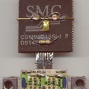
Step 4: The Circuit


The circuit is very simple. The eight pin microcontroller was mounted on a piece of scrap copper clad board after cutting out eight islands for the eight leads. An electrolytic capacitor was connected across the supply leads. A crystal taken from an old watch was fitted across leads 2 & 3. Two 15 pf capacitors are also to be fitted, but mine seems to work without it. Your Mileage May Vary. The MCLR/Vpp lead was pulled up to Vdd with a 10K resistor.
The remaining three leads connect to three resistors forming a crude weighted resistor DAC.
GPIO0 has a 47 K resistor.
GPIO1 has a 22 K resistor. This should be half the previous value, about 23.5 K, but this value is close enough.
GPIO2 has a 12 K resistor, close to the ideal value of 11K.
The other ends of the resistors are connected together, and I used a series resistor of 1 Megohm and connected it to the Line in jack of the sound card in my computer using shielded cable.
The thin wires in the picture are actually enamelled copper, and so will not short to one another if they touch. They go to a programming and power supply socket at the top of the board.
Step 5: Displaying the Clock

Since the Cathode Ray Oscilloscope is a beast rarely found outside of its favourite haunts, I decided to use the computer sound card and recording utility to display the output of the clock.
As shown in the screenshot, the recording control has to be used in order to select the LINE IN socket as source (or whatever else you are connecting it to).
I used a program called Free Audio Editor to capture the output of the clock and view it. As you can see, the results are not very good.
Step 6: Decode the Waveform

Here is my screenshot of a capture of the output from the clock. The waveforms show the time changing from 12:02:59 to 12:03:00. The two waveforms are separated by one second, and was edited to make them appear close to each other.
The problem with visibility here is that the program draws lines in between the dots, joining them. In an actual oscilloscope display, the lines between those dots will be very faint because the electron beam is travelling fast, so only the spots will be visible.
The best way of displaying the clock was that used for the introductory screenshot - using a windows based oscilloscope program which displays waveforms captured from the sound card. Just search the web for "winscope".
Or there might be some audio editing software out there that displays the waveform as scattered dots rather than jointed lines.
Step 7: Windows Based Oscilloscope

The picture shows a screen shot of the program I used to display the clock. The program is also attached, in case somebody wants to play with it. It says "for win 95" but it worked in my win xp system. It might work in Vista, too.
Attachments

Step 8: Setting the Time


Originally, I had intended to have a serial reception routine monitoring the GPIO3 line for setting the clock. However, the slow clock rate of 32 KHz was too low for any decent baud rate, and the overheads of keeping time and display on a PIC without interrupts meant that serial communication will in most cases fail to work.
However, that one input could be used as a "fast set" input - pull that low, and the clock increments at a fast rate. Release it when the correct time is reached and the clock runs on as usual. This has not been implemented, however. At present the only way to have the clock keep correct time is to switch it on at 12 noon precisely.
The pictures show a different sort of waveform from the clock, and the changes in the program which caused these to happen.
The program files and the hex file are included as well, so that you can, if you wish to, duplicate my efforts.
And why would you want to do that?
The clock is a very compact instrument. Power it from three button cells and it can be made small enough to be worn as a ring.
The only disadvantage is the need to carry around a storage oscilloscope and its power supply in order to read the time.
Since the output is an audio waveform, this sort of coding can be used to transmit telemetry or beacon data through a voice link. But as a clock, I am afraid this gadget will rate among one of those elaborate, but completely useless, contraptions which do some commonplace thing in a roundabout way.


![Tim's Mechanical Spider Leg [LU9685-20CU]](https://content.instructables.com/FFB/5R4I/LVKZ6G6R/FFB5R4ILVKZ6G6R.png?auto=webp&crop=1.2%3A1&frame=1&width=306)


