

Introduction: Plug-in LED Color Fading Night Light


Want to add a little fun to those boring old plug-in night-lights? Why not make it more exciting with an RGB LED? I will be showing you how to do this with a couple simple parts that you could get from any online electronic component supplier. You can get all these parts for less than $10, including the night light!
It also makes a great gift! :)
This is a contest entry in the Elemental LED contest, the Hurricane Lasers contest, and the Hack It! contest, so if you like it, vote for me!
Step 1: How It Works

The brains of the operation is the ATtiny85 chip from Atmel. You could also substitute it with a ATtiny45/25.
The power for the circuit is provided with a 3 volt CR2032 battery. If we were to implement a AC to DC converter circuit, the whole thing would be way too large to fit inside the small plastic body of the night light. The small coin cell battery works much better.
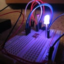
The lamp senses the ambient light in the room with a LDR (light dependent resistor) and then takes the returned value and determines if the lights are on or off. If it detects that the lights are on, then it will set the LED pins to LOW, or off. If it detects that the lights are off, it will turn on the LEDs begin the color fading sequence. When you turn the lights back on, it will stop.
Simple enough, right?
Step 2: Parts List


You will need:
1x ATtiny85/45/25
1x Common Cathode RGB LED
1x LDR (light dependent resistor) (sometimes called CdS Cell) (you might not need this part)
1x 10k Ohm resistor
1x CR2032 3 volt Battery
1x CR2032 Battery holder
1x Light sensing plug-in wall night light
1x Arduino Uno (for programming the ATtiny)
Step 3: Program the ATtiny

First, we need to tell the ATtiny chip what to do. Follow this helpful page for instructions on how to do this with an Arduino.
After you have followed the instructions on there to get the Arduino prepped for programming, upload this sketch to the ATtiny.
//CODE BEGINS HERE
const int redPin = 2;
const int grnPin = 1;
const int bluPin = 0;
const int sensor = 3;
void setup()
{
pinMode(redPin, OUTPUT);
pinMode(grnPin, OUTPUT);
pinMode(bluPin, OUTPUT);
pinMode(sensor, INPUT);
}
void loop() {
if (analogRead(sensor) <= 200)
{
redtoyellow();
yellowtogreen();
greentocyan();
cyantoblue();
bluetomagenta();
magentatored();
}
else if (analogRead(sensor) >= 201)
{
digitalWrite(redPin, LOW);
digitalWrite(grnPin, LOW);
digitalWrite(bluPin, LOW);
}
}
void redtoyellow()
{
digitalWrite(redPin, HIGH);
digitalWrite(bluPin, LOW);
// fade up green
for(byte i=1; i<100; i++) {
byte on = i;
byte off = 100-on;
for( byte a=0; a<100; a++ ) {
digitalWrite(grnPin, HIGH);
delayMicroseconds(on);
digitalWrite(grnPin, LOW);
delayMicroseconds(off);
}
}
}
void yellowtogreen()
{
digitalWrite(grnPin, HIGH);
digitalWrite(bluPin, LOW);
// fade down red
for(byte i=1; i<100; i++) {
byte on = 100-i;
byte off = i;
for( byte a=0; a<100; a++ ) {
digitalWrite(redPin, HIGH);
delayMicroseconds(on);
digitalWrite(redPin, LOW);
delayMicroseconds(off);
}
}
}
void greentocyan()
{
digitalWrite(grnPin, HIGH);
digitalWrite(redPin, LOW);
// fade up blue
for(byte i=1; i<100; i++) {
byte on = i;
byte off = 100-on;
for( byte a=0; a<100; a++ ) {
digitalWrite(bluPin, HIGH);
delayMicroseconds(on);
digitalWrite(bluPin, LOW);
delayMicroseconds(off);
}
}
}
void cyantoblue()
{
digitalWrite(bluPin, HIGH);
digitalWrite(redPin, LOW);
// fade down green
for(byte i=1; i<100; i++) {
byte on = 100-i;
byte off = i;
for( byte a=0; a<100; a++ ) {
digitalWrite(grnPin, HIGH);
delayMicroseconds(on);
digitalWrite(grnPin, LOW);
delayMicroseconds(off);
}
}
}
void bluetomagenta()
{
digitalWrite(bluPin, HIGH);
digitalWrite(grnPin, LOW);
// fade up red
for(byte i=1; i<100; i++) {
byte on = i;
byte off = 100-on;
for( byte a=0; a<100; a++ ) {
digitalWrite(redPin, HIGH);
delayMicroseconds(on);
digitalWrite(redPin, LOW);
delayMicroseconds(off);
}
}
}
void magentatored()
{
digitalWrite(redPin, HIGH);
digitalWrite(grnPin, LOW);
// fade down blue
for(byte i=1; i<100; i++) {
byte on = 100-i;
byte off = i;
for( byte a=0; a<100; a++ ) {
digitalWrite(bluPin, HIGH);
delayMicroseconds(on);
digitalWrite(bluPin, LOW);
delayMicroseconds(off);
}
}
}
//CODE ENDS HERE
Step 4: Solder It Together

Solder it onto the smallest piece of perfboard you can fit it onto, or even better, don't use a board at all, and just free-hand solder it.
Step 5: Gut the Night-light


First, start by taking the clear plastic cover off the top. It should just easily unclip from the white stand.. Then remove the lightbulb. Next, take a pair of pliers and carefully remove the top part of white plastic that the lightbulb was screwed into. Now you can see the circuit board. Remove this.
Take the circuit board and remove the LDR if possible. You can use this one instead of buying a new one. Now break everything off the board except for the plugs for the wall. Hot glue the board so that no metal wires/parts are exposed (this is for insulating purposes) and slide the hot-glued board back into the night light with the plugs facing out, like before.
Step 6: Stuff in the Custom Circuit


Now we have to try to fit the circuit inside the lamp. Fit it however you can, but make sure that the LED is pointing up, in the same place that the light bulb was before, and that the the LDR is also in the same place it originally was, so that it can still sense light.
Step 7: Finish It Up and Make It Look Nice!

Now that you have the electronics all figured out, you can go ahead and hot-glue everything in place. Get the two circuit boards covered in hot glue on the places that they might be touching, so that you don't short-circuit anything on the board we made. Then, hot glue the clear plastic cover back in place and let it dry.
Step 8: Watch the Magic!
Obviously, you won't really have to plug it into the wall because it is powered by a battery, but it makes it look better (in my mind) because it actually looks like it's supposed to be all colorful, and you can't see all the messy soldering and hot-gluing behind it.
If you leave it plugged in in the bathroom, people will be pleasantly surprised when they see the bright fading colors at night!

Participated in the
Hurricane Lasers Contest

Participated in the
LED Contest with Elemental LED

Participated in the
Hack It! Contest


