

Introduction: Portable Arduino Uno Temperature and Humidity Sensor With LCD Screen


Hey everybody. I have gotten a lot of great ideas from instructables over the years. As this is my first 'ible, I figure I would share something I made as well. I am entering this into the Full Spectrum Laser Contest 2016. If I were to win, I would be able to 3d print a case for this project and use the laser engraver to etch an awesome design into the case. If you enjoy this 'ible, please vote for me.
In this Instructable, I am going to show you how I made a temp and humidity sensor with an Arduino Uno. My end goal is to make one with an Attiny84 and etch a PCB for it. While I do have the parts and pieces to do this, the weather outside is not cooperating. It is hard to etch a board in my garage at less than 10 degrees Fahrenheit. That will be a different instructable for a later date.
Without further delay, here is my instructable. Thanks again for taking time to read my project.
Step 1: Parts BOM


To start out, the following is required for this project:
All parts can be purchased at sparkfun or adafruit. Or you can do as I do and salvage as much as you can from old devices.
- Arduino (I used an UNO R3, but 5V any will work)
- Breadboard
- DHT11 temperature and humidity sensor
- 10k ohm potentiometer
- 16x2 LCD screen
- tactile button
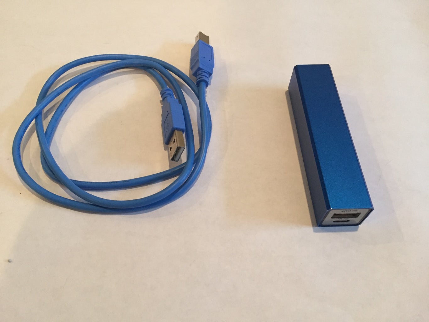
- USB A-B cable
- Power Bank
- Jumper Wires
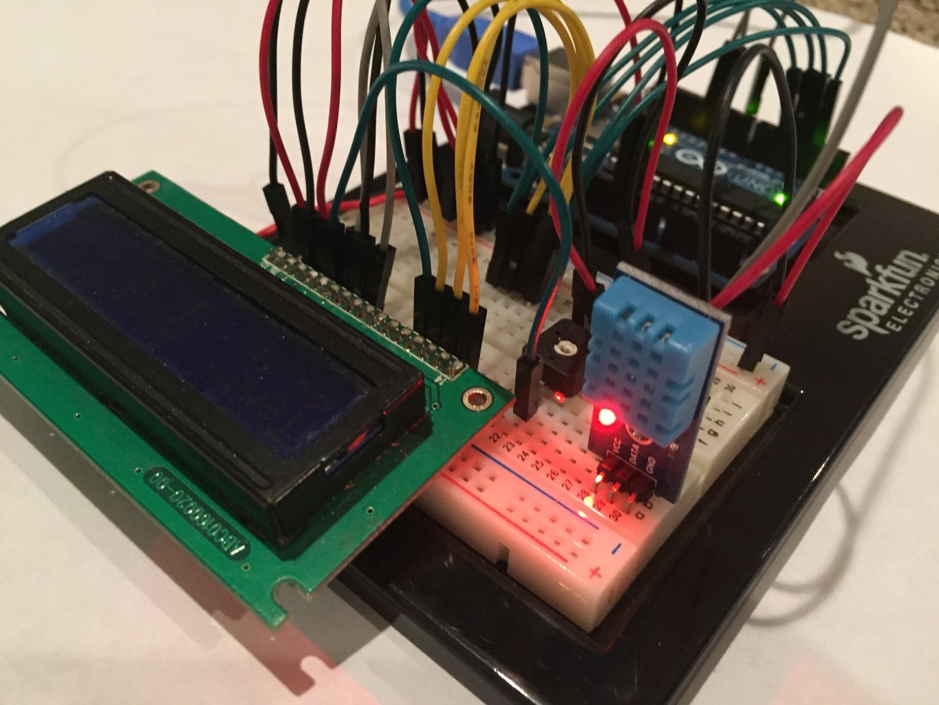
Step 2: Building the Circuit
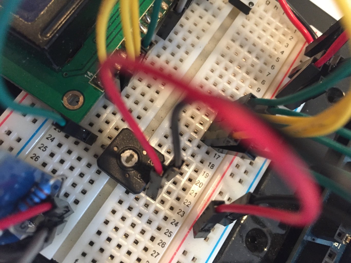

Now it is time to attach all the wires to the devices. Please refer to the Fritzing schematic (please note I do not have jumper wires between the two power rails on the breadboard. you will need them if you use both):
The LCD display I am using was recovered from an old fire alarm annunciator panel. Pins 15 & 16 are located before Pin 1 and instead of Pin 16 being Gnd, it is actually 5v and Pin 15 is Gnd. Please double check your own display and make sure your pins are correct. As my display pinout is most likely different from almost everybody else, I have made the Fritzing schematic with the "standard" display instead of my exact pinout.
Uno
Gnd --> negative rail on breadboard
5v --> positive rail on breadboard
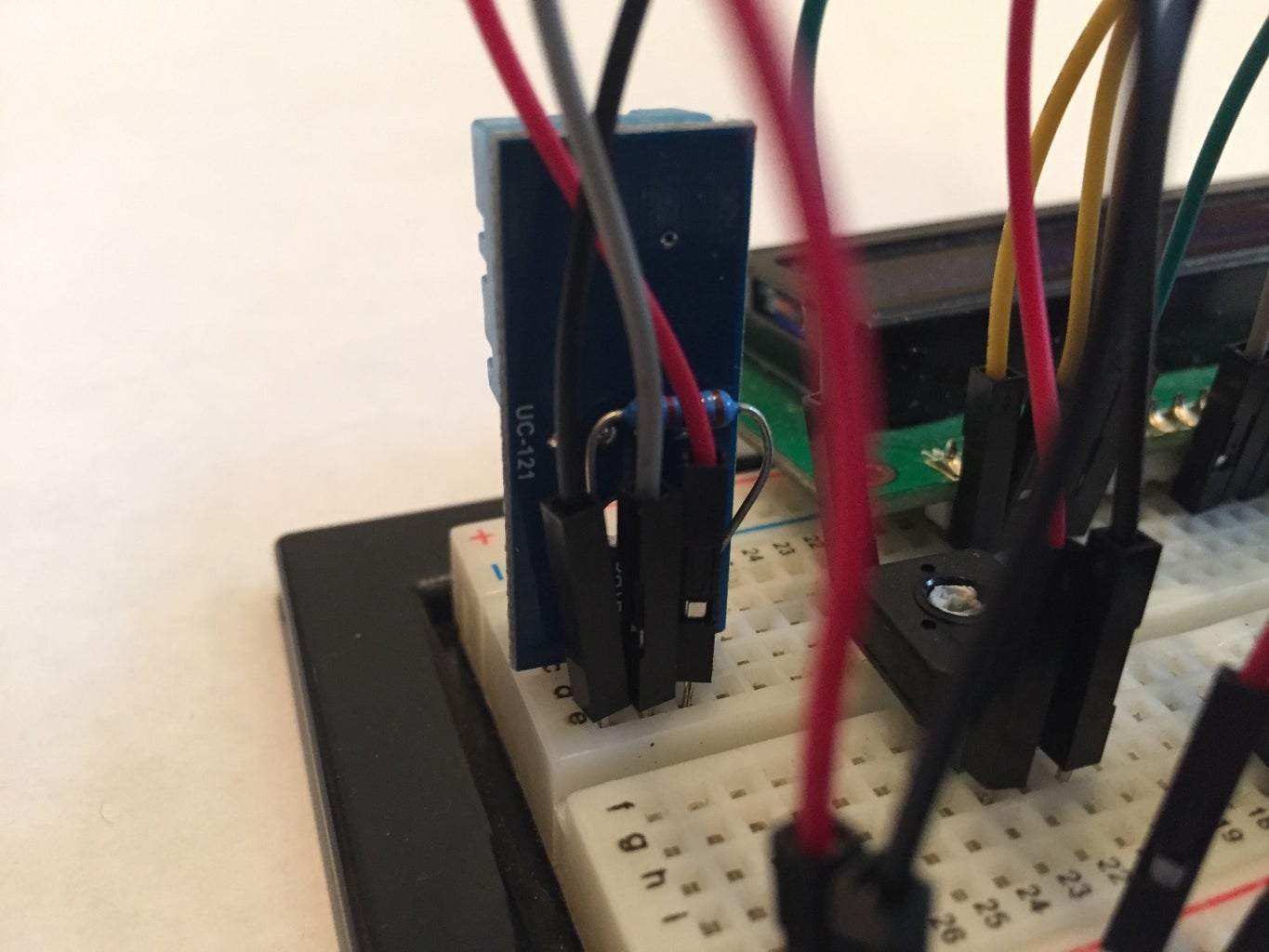
DTH11
Pin1 --> 5v and 10k ohm resistor
Pin2 --> Arduino Pin8 and 10k ohm resistor
Pin3 --> no connection
Pin4 --> Gnd
16x2 LCD Screen
Pin1 --> Gnd
Pin2 --> 5v
Pin3 --> 10k ohm potentiometer wiper pin ( middle pin. the other two pins on the POT go to 5v and Gnd)
Pin4 --> Arduino Pin12
Pin5 --> Gnd
Pin6 --> Arduino Pin11
Pin7 --> no connection
Pin8 --> no connection
Pin9 --> no connection
Pin10 --> no connection
Pin11 --> Arduino Pin5
Pin12 --> Arduino Pin4
Pin13 --> Arduino Pin3
Pin14 --> Arduino Pin2
Pin15 --> 5v
Pin16 --> Tactile button (other side of tack button goes to Gnd)
Step 3: The Code
Below is the code:
I used the DHT library from Adafruit.
https://github.com/adafruit/DHT-sensor-library
--CODE--
// include the library code:
#include "DHT.h"
// set the DHT Pin #define DHTPIN 8
// initialize the library with the numbers of the interface pins
LiquidCrystal lcd(12, 11, 5, 4, 3, 2);
#define DHTTYPE DHT11
DHT dht(DHTPIN, DHTTYPE);
void setup() {
// set up the LCD's number of columns and rows:
lcd.begin(16, 2);
dht.begin();
// Print a message to the LCD.
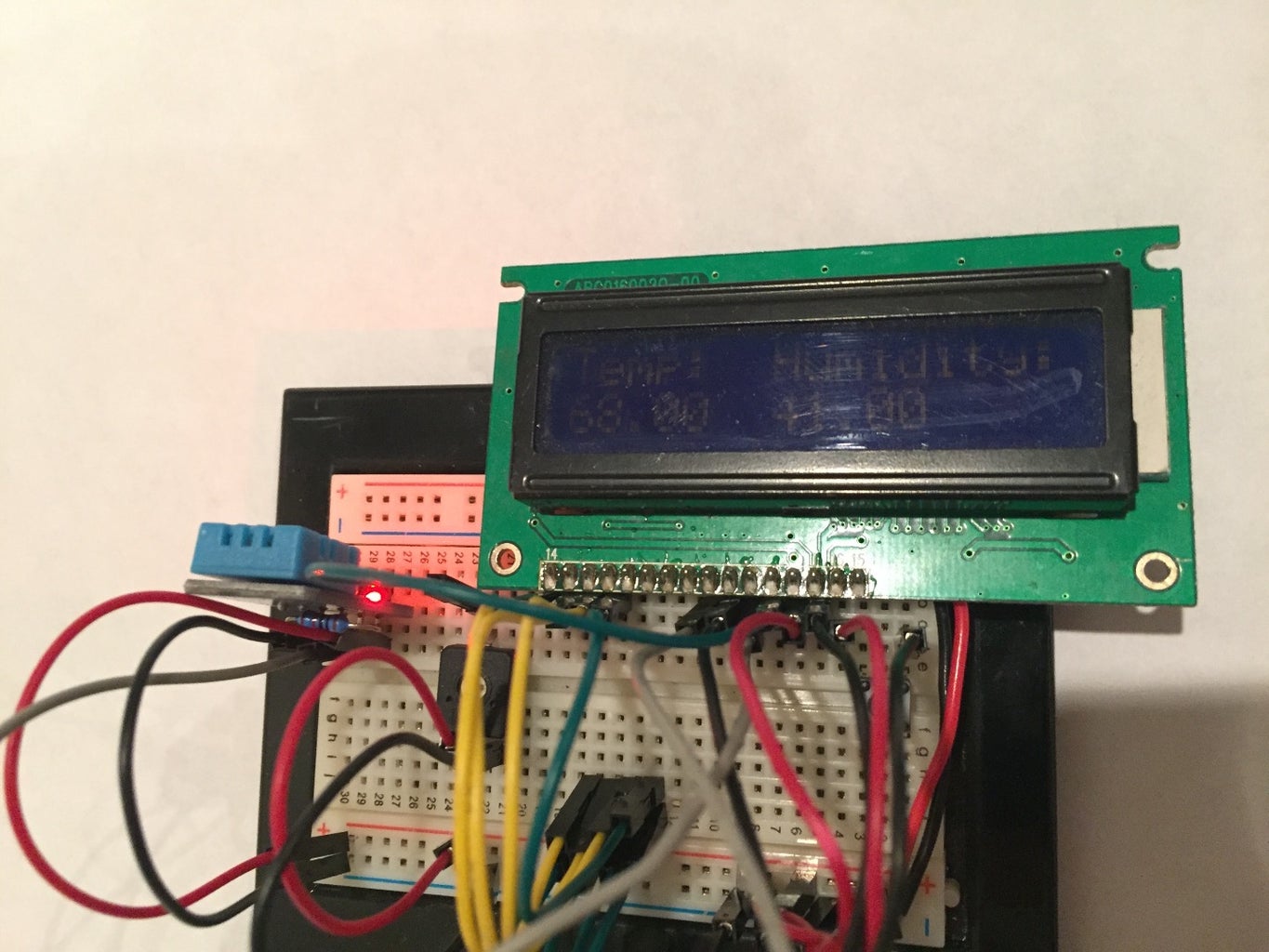
lcd.print("Temp: Humidity:"); }
void loop() {
delay(500);
// set the cursor to column 0, line 1
// (note: line 1 is the second row, since counting begins with 0):
lcd.setCursor(0, 1);
// read humidity
float h = dht.readHumidity();
//read temperature in Fahrenheit
float f = dht.readTemperature(true);
if (isnan(h) || isnan(f)) {
lcd.print("ERROR");
return;
}
lcd.print(f);
lcd.setCursor(2,1);
lcd.print(char(223));
lcd.setCursor(3,1);
lcd.print(" F");
lcd.setCursor(7,1);
lcd.print(h);
lcd.setCursor(9,1);
lcd.print(char(37));
}
--CODE--
Attachments

Step 4: Finished!
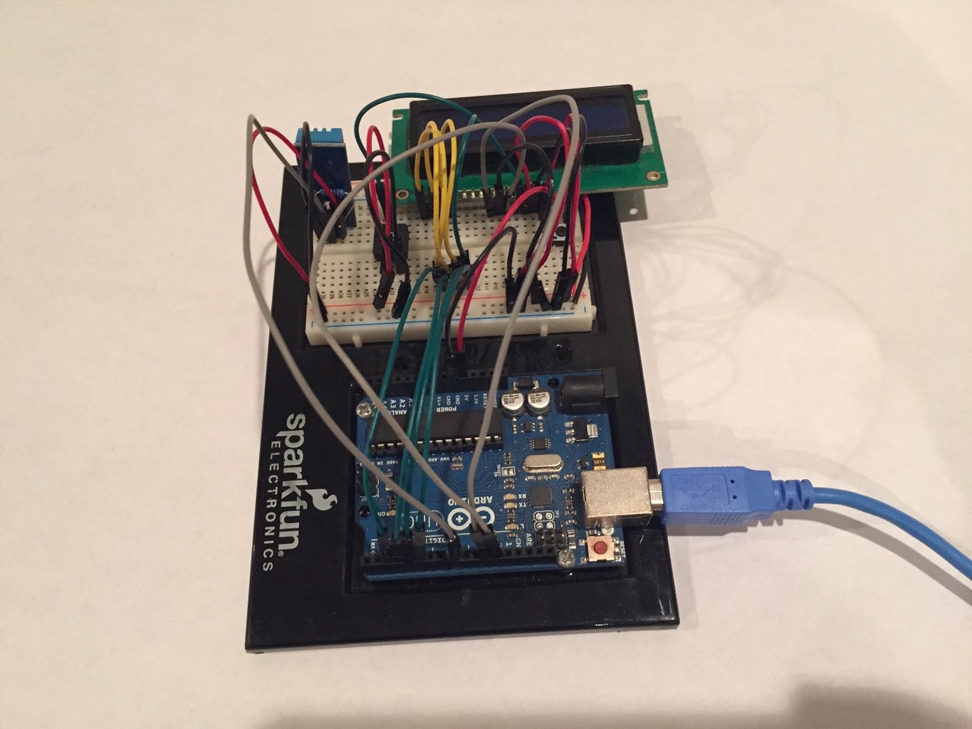
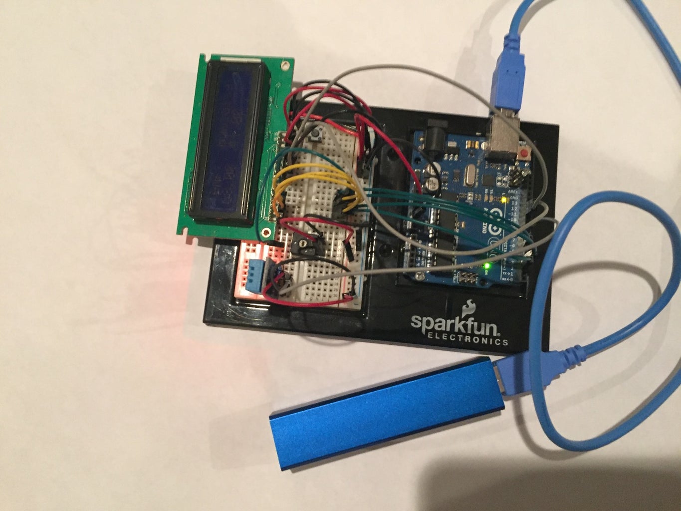
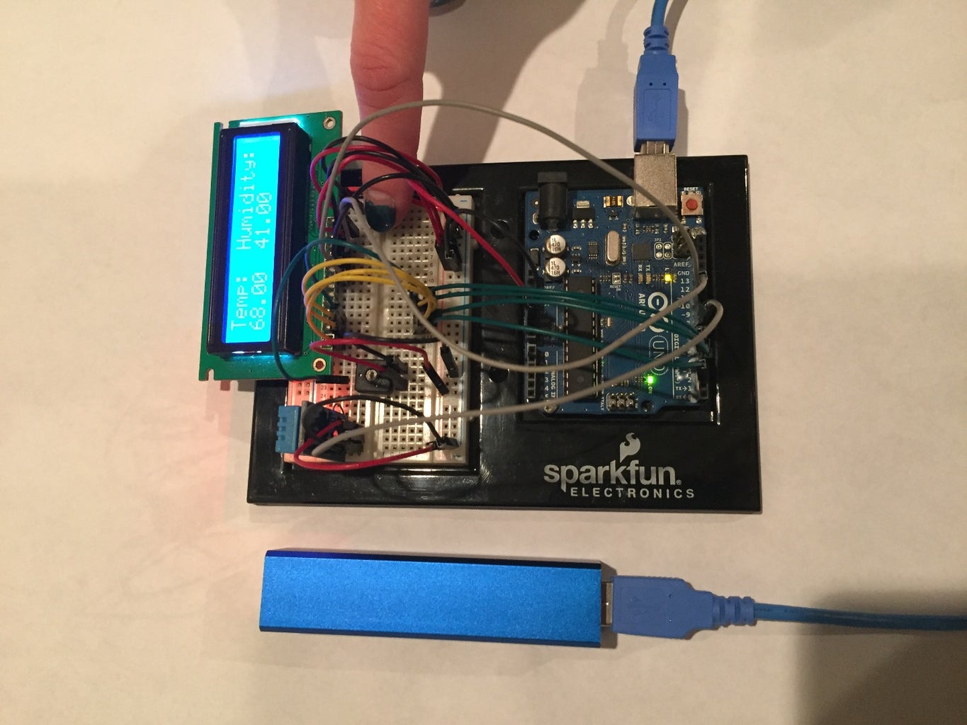
After all of the wiring, plug your power bank to the Arduino.
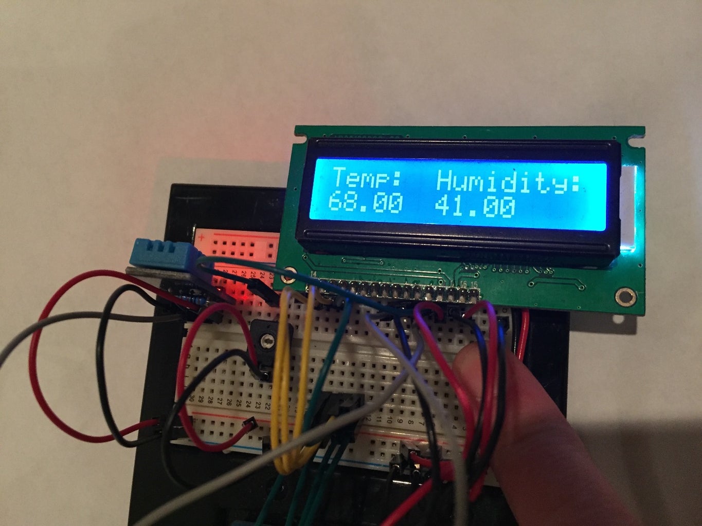
Your LCD display and DHT11 should start up. Press the tact button and your LCD backlight should light up.
Now you have a portable temperature and humidity sensor with a real time display.
This has helped me determine my draftiest windows in my house and how best to set my house ventilation.
Thanks again for taking the time to read my first instructable.
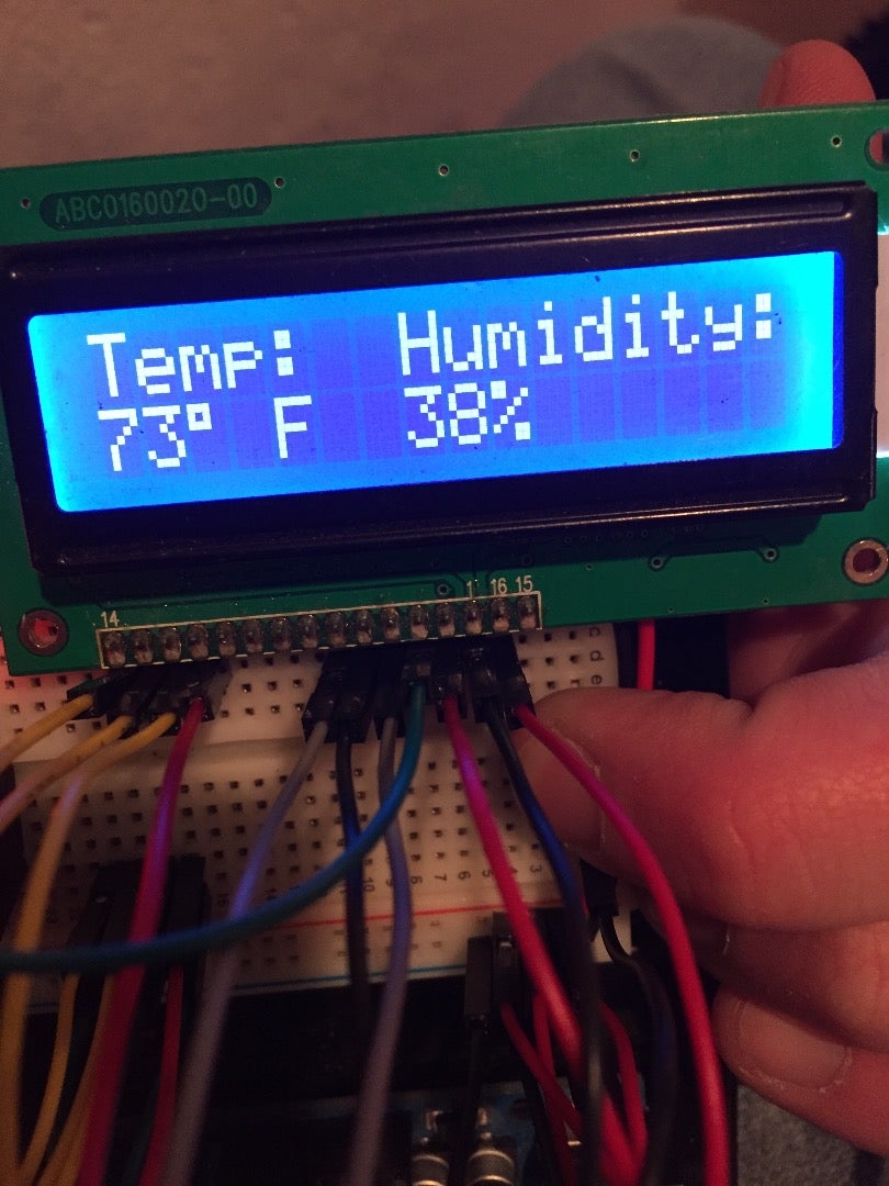
UPDATE #1
Thanks to Waggabob, the LCD display has been updated to display the degree symbol. I also added the % symbol to the humidity. (see last picture for updated display)

Participated in the
Full Spectrum Laser Contest 2016

Participated in the
Digital Life 101 Challenge


