Introduction: Post-Processing Tool Paths


The Toolpaths produced in ArtCAM must be translated into a different format as an exported file for a specific machine tool controller. The collective name for one of these files is NC data and the operation is called Post-Processing which is accessed via the Save Toolpaths option. ![]()
Step 1: Post-Processing Tool Paths Tutorial
1 Open a previously machined model. 8 - machine-ted_completed.art.
2 Activate the Project panel if not already visible.
3 Highlight Toolpaths from the List then Save Toolpaths ![]() from the Toolpath Operations area in the lower Project panel.
from the Toolpath Operations area in the lower Project panel.
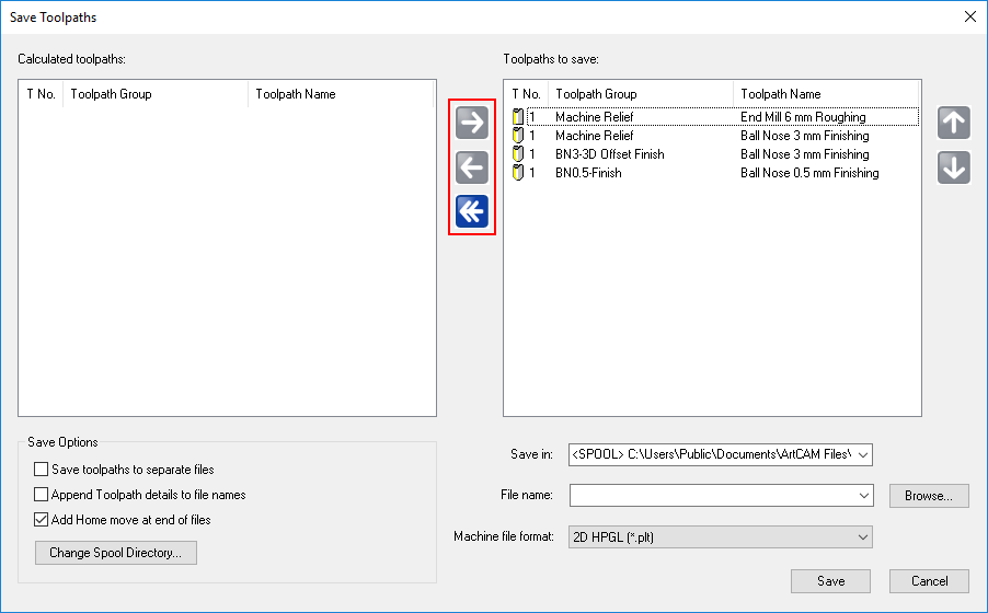
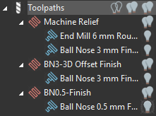
When the Save Toolpaths form is opened all existing toolpaths are listed in the right hand window (as Toolpaths group was highlighted). Toolpaths are selected and transferred from one side to the other using the central Arrow buttons as highlighted above.
All the files in the right hand window (Toolpaths to save/post process) will be included for output into a single NC data file. If the machine tool uses a manual tool changer then it will only be possible to include Toolpaths in the NC data file that share the same cutting tool.
If the machine tool has an automatic tool changer then any combination of the available toolpaths can be include in the NC data file (as long as the selected machine supports it).
Post Processing of Toolpaths for a Manual Tool Changer
1Shift select all Toolpaths apart from the first Machine Relief-End Mill 6mm Roughing.
2 Click the Left arrow ![]() to transfer into the Calculated toolpaths.
to transfer into the Calculated toolpaths.

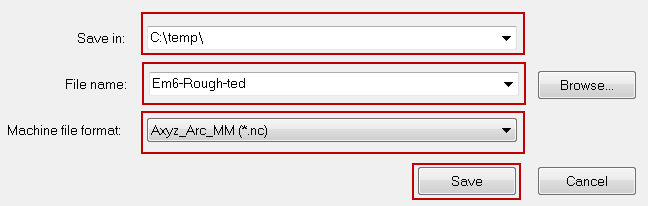
3 Browse… to a suitable location (e.g C:\Temp)and enter File name as Em6-Rough-ted.
4 Select Open on the Browse window to return to the Save Toolpaths window.
5 From Machine file format select Axyz_Arc_MM(*.nc).
This machine does not support an automatic tool changer hence only Toolpaths that use the same tool can be included in the ncdata output file.
6 Select Save to post process the Toolpath.
7 Select the left arrow ![]() to transfer the toolpath back to the left window.
to transfer the toolpath back to the left window.
8 Select the toolpath Machine Relief-Ball nose 3mm finishing and then the right arrow. ![]()
9 Enter a filename BN3-finish-ted and then Save.
10 Repeat the above procedure for the remaining two Toolpaths providing suitable file names.
11 Browse to the C:\Temp directory to see the saves toolpaths.
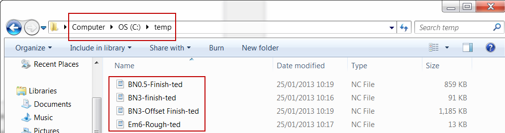
All the post-processed Toolpaths have been saved outside ArtCAM and translated in the format required for an Axyz machine controller. These files can now transferred to the machine controller itself, ready for manufacture.
If the Toolpath itself is modified within ArtCAM, the above process must be repeated for that specific file.C:\Temp as a location is not recommended for production. A structured folder system according to best practice must be utilised.
12 Do not close the model as it is required again in the next section.
Post Processing of Toolpaths for an Automatic Tool Changer
If a Machine Tool is fitted with an Automatic Tool Changer then the control of this feature will be available in the Post Processor translation.
If toolpaths containing different tools are passed over to the right hand window of the Save Toolpaths form and the selected Post Processor does not support an Automatic Tool Changer then a box with an error message will appear.
1 Using the arrow ![]() Transfer all the toolpaths into the right hand window as shown.
Transfer all the toolpaths into the right hand window as shown.

The Vertical arrows can be used to reorder the toolpaths for a single output file.
2 Ensure the same machine output file is selected as before.
3 Select Save to output the combined files.
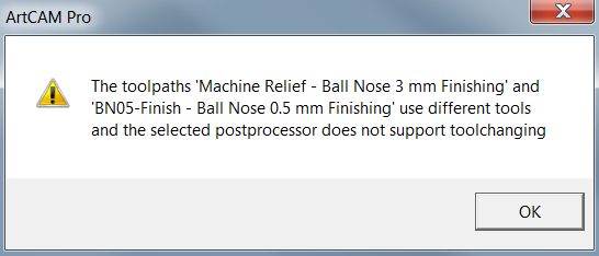
The operation has failed and the above error message appears. The files were unable to be processed for two reasons.
- The selected Machine (post processor) does not support tool changing itself.
- All tools are currently identified as Tool number 1. The Tool Number is essential to identify the location of an individual Tool in the tool changer or carousel.
![]()
The Tool Number can be specified in a number of ways.
- Entering the tool number within the defined tool of the toolpath. The Toolpath must be recalculated.

- Entering/Editing the default tool number defined in the Tool database.

- The quickest way is to change the tool number by first highlighting the tool in the Toolpaths Project Panel.

- Then changing the Tool number in the lower window before selecting Apply.
4 Use any of the methods described above to assign different Tool numbers as shown in the image below.
5 Select Save Toolpaths ![]() from the Toolpath Operations area.
from the Toolpath Operations area.
6 Move all the Toolpaths to the right hand window.
7 Reorder the Toolpaths as required.

8 Enter file name as Machine Ted.
9 Change the Machine output file to Axyz_MultiTool_Arc_MM.
10 Select Save.
No Error message is displayed and now allows the files to be saved as one.
11Browse to the C:\Temp directory to see the saved toolpaths.
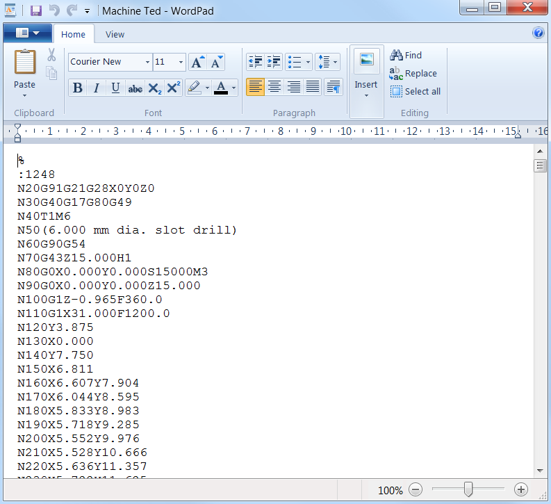
NC code can be viewed in WordPad for analysis or editing if required.
12 Right mouse click on the Toolpath Machine Ted an open with WordPad.

The outputted NC code can be viewed.