

Introduction: Arduino Serial Port Shield for Linkit One


I use a lot of Lantronix WiBoxes. They let you hook legacy serial devices to a Wifi network. I use them for Digital Signage and Security monitoring apps. I usually only use one port on them.
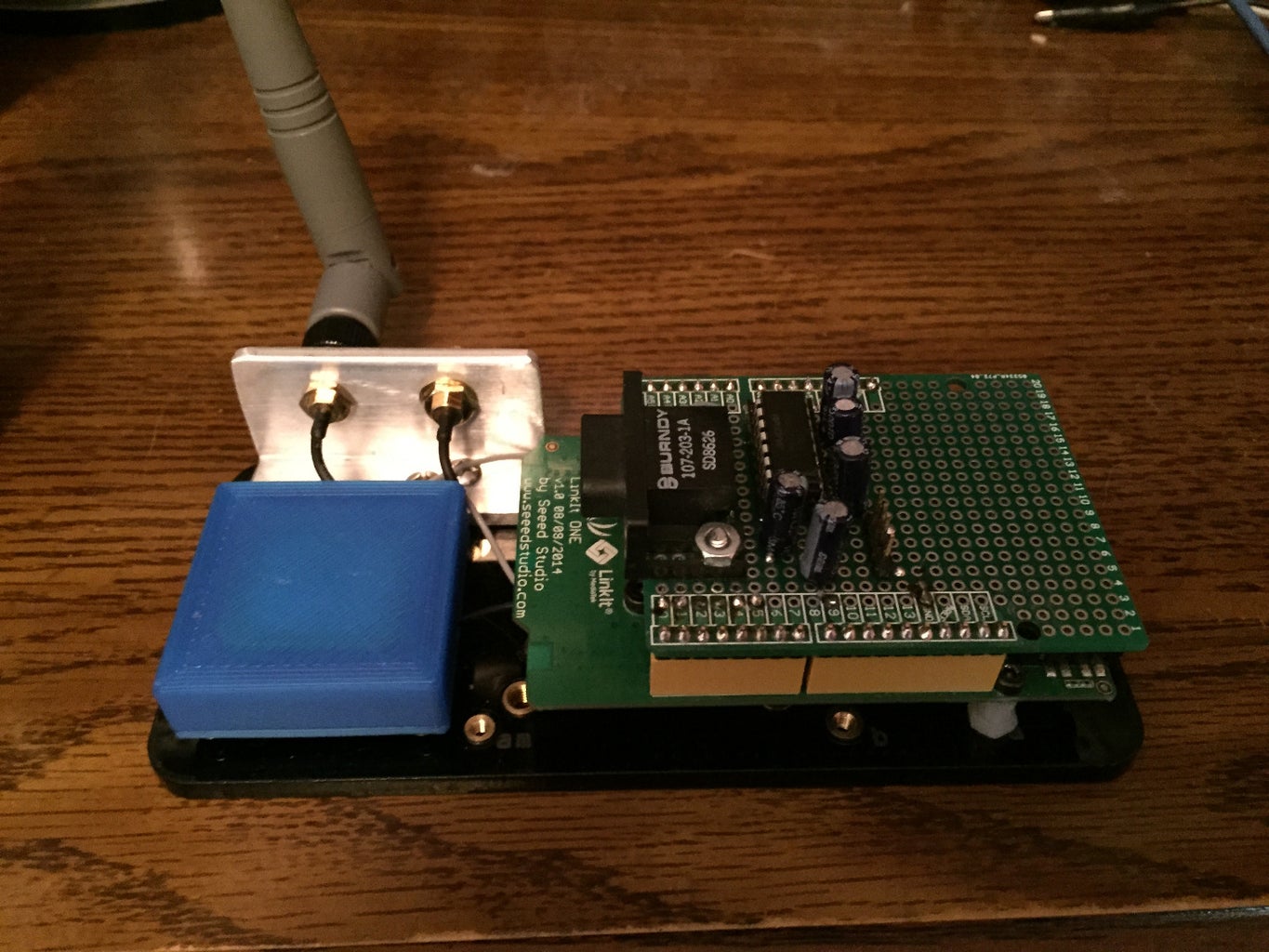
I made a legacy serial port adapter for the Linkit One's serial pins. This way I can replace the Wiboxes on my devices without making any hardware changes.It works equally well on most Arduino compatible boards.
Initially I wrote a program for the Linkit that emulates the existing Wifi connectivity I use. But thats boring. The next version will use the Linkit's GSM capability to allow SMS connectivity. For security apps I will use both. Having a dual redundant connection is a big improvement over the old way.
Step 1: Schematic

Pretty Simple. Just follow the data sheet and you cant go wrong. I run it off the 3.3V line and it seems fine. That way I don't need a level shifter on the data pins. If you want to run it off 5V you should probably add a resistor and 3.3V Zener on the rx line before it get to the Linkit One digital pin 0.
Step 2: Assembling the Shield

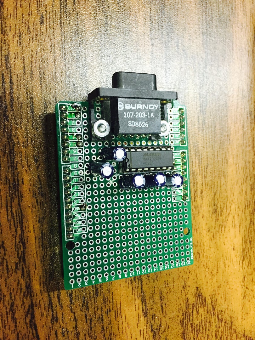


I used a standard Arduino prototyping shield. I chose the MAX232CPE since I have plenty on hand. These need 1uF caps. Other chips need Larger or smaller caps so be sure to use those that match the chip you select.
I followed the schematic and placed the components to the rear of the shield. I originally thought I would place the connector so it would be on the same side as the Linkit One connectors but this orientation suits a specific application I have in mind. Lay yours out to match your own application.
I wired RTS and CTS pins to digital I/O pins on the Linkit. While not supported by the Serial1 routines I will implement them manually when needed. Some devices draw power from them too.
It clears the GPS antenna too.
Step 3: Testing & Enhancements


Looks like I misjudged the serial cable length I needed. Oh well, some protoboard jumpers will do for now. For testing lets try a Magtek serial port mag stripe reader. I got these from a surplus house that claims they were made for Diebold and intended for use in gas pumps. I found a spec sheet online that explained all the dip switch settings. It looks like only the top board was custom made for Diebold. These read tracks 1 & 2.
That seems to work great for input. The raw data is good.
Next I made another sketch to parse it. Had to do a little work to read just the data I wanted.
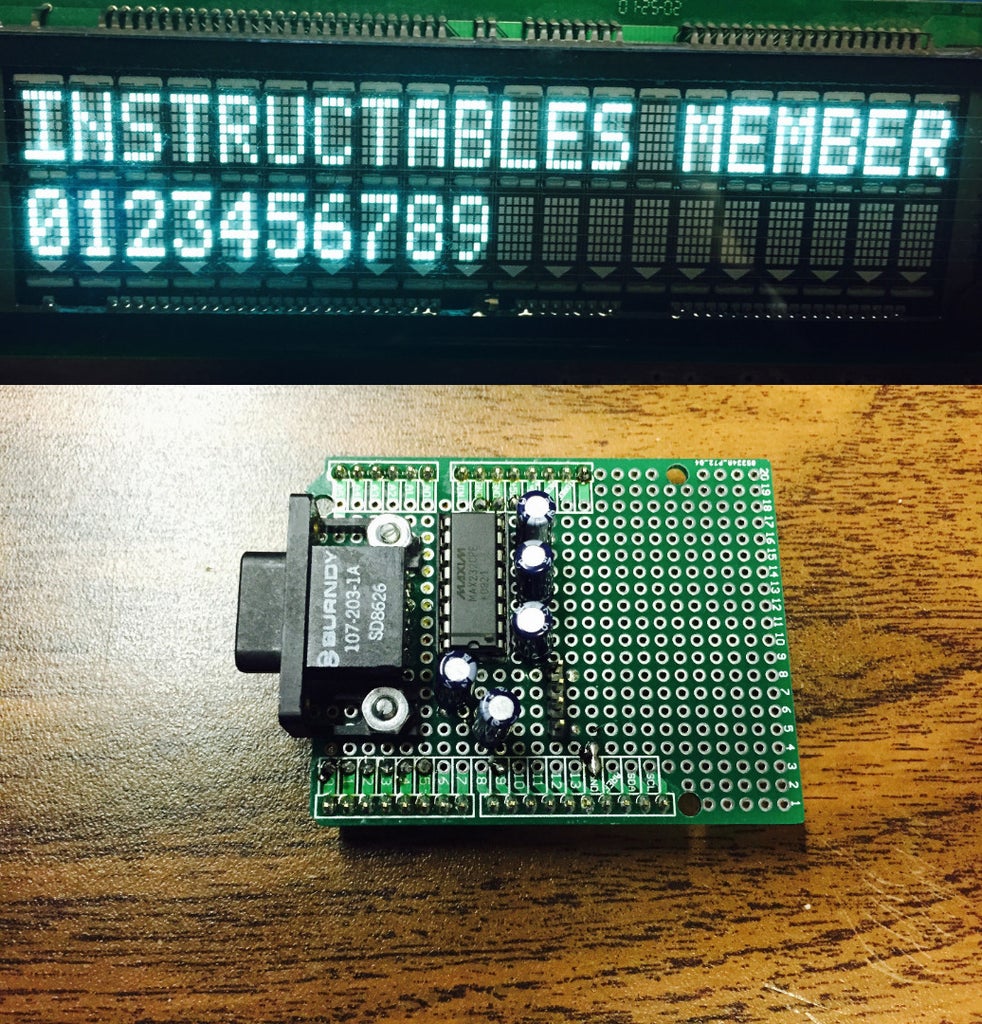
So for output lets try a Futaba VFD Serial Display. I encoded a dummy card so I don't have to worry about posting the output for everyone to see.
OK, Legacy Serial devices work. I have some I want to start working on now.
I left plenty of room in case I want to add circuitry.
I cant really think of any right now but I'm open to suggestions.


Participated in the
Tech Contest

Participated in the
Arduino All The Things! Contest


