

Introduction: Simple Arduino Metal Detector


*** A new version has been posted that is even simpler: https://www.instructables.com/Minimal-Arduino-Metal-Detector/ ***
Metal detection is a great past-time that gets you outdoors, discover new places and maybe find something interesting. Check your local regulations on how to act in case of an eventual find, in particular in case of hazardous objects, archeological relics or objects of significant economic or emotional value.
Instructions for DIY metal detectors are plenty, but this recipe is particular in the sense that it requires very few components in addition to an Arduino microcontroller: a common capacitor, resistor and diode form the core, together with a search coil that consist of circa 20 windings of electrically conducting cable. LED’s, a speaker and/or headphone are then added for signalling the presence of metal near the search coil. An additional advantage is that all can be powered from a single 5V power, for which a common 2000mAh USB power is sufficient and will last many hours.
To interpret the signals and to understand what materials and shapes the detector is sensitive to, it really helps to understand the physics. As a rule of thumb, the detector is sensitive to objects at a distance or depth up to the radius of the coil. It is most sensitive to objects in which a current can flow in the plane of the coil, and the response will correspond to the area of the current loop in that object. Thus a metal disc in the plane of the coil will give a much stronger response than the same metal disc perpendicular to the coil. The weight of the object does not matter much. A thin piece of aluminium foil oriented in the plane of a coil will give a much stronger response than a heavy metal bolt.
Step 1: Working Principle

When electricity starts flowing through a coil, it builds up a magnetic field. According to Faraday’s law of induction, a changing magnetic field will result in an electric field that opposes the change in magnetic field. Thus, a voltage will develop across the coil that opposes the increase in current. This effect is called self-inductance, and the unit of inductance is Henry, where a coil of 1 Henry develops a potential difference of 1V when the current changes by 1 Ampere per second. The inductance of a coil with N windings and a radius R is approximately 5µH x N^2 x R, with R in meters.
The presence of a metallic object near a coil will change its inductance. Depending on the type of metal, the inductance can either increase or decrease. Non-magnetic metals such as copper and aluminium near a coil reduce the inductance, because a changing magnetic field will induce eddy currents in the object that reduce the intensity of the local magnetic field. Ferromagnetic materials, such as iron, near a coil increase its inductance because the induced magnetic fields align with the external magnetic field.
The measurement of the inductance of a coil can thus reveal the presence of metals nearby. With an Arduino, a capacitor, a diode and a resistor it is possible to measure the inductance of a coil: making the coil part of a high-pass LR filter and feeding this with a block-wave, short spikes will be created at every transition. The pulse length of these spikes is proportional to the inductance of the coil. In fact, the characteristic time of an LR filter is tau=L/R. For a coil of 20 windings and a diameter of 10 cm, L ~ 5µH x 20^2 x 0.05 = 100µH. To protect the Arduino from overcurrent, the minimum resistance is 200Ohm. We thus expect pulses with a length of about 0.5 microsecond. These are difficult to measure directly with high precision, given that the clock frequency of the Arduino is 16MHz.
Instead, the rising pulse can be used to charge a capacitor, which can then be read out with the Arduino analog to digital converted (ADC). The expected charge from a 0.5 microsecond pulse of 25mA is 12.5nC, which will give 1.25V on a 10nF capacitor. The voltage drop over the diode will reduce this. If the pulse is repeated a few times, the charge on the capacitor rises to ~2V. This can be read out with the Arduino ADC using analogRead(). The capacitor can then be quickly discharged by changing the readout pin to output and setting it to 0V for a few microseconds.The whole measurement takes about 200 microseconds, 100 for the charging and resetting of the capacitor and 100 for the ADC conversion. The precision can be greatly enhanced by repeating the measurement and averaging the result: taking the average of 256 measurements takes 50ms and improves the precision by a factor 16. The 10-bit ADC achieves the precision of a 14-bit ADC this way.
This measurement obtained is highly nonlinear with the inductance of the coil and therefore not suitable to measure the absolute value of the inductance. However, for metal detection we are only interested in tiny relative changes of the coil inductance due to the presence of nearby metals, and for that this method is perfectly suitable.
The calibration of the measurement can be done automatically in software. If one can assume that most of the time there is no metal near the coil, a deviation from the average is a signal that metal has come close to the coil. Using different colours or different tones allows to discriminate between a sudden increase or a sudden decrease in the inductance.
Step 2: Required Components
Electronic core:
Arduino UNO R3 + prototype shield OR Arduino Nano with 5x7cm prototype board
10nF capacitor
Small signal diode, e.g. 1N4148
220-ohm resistor
For power:
USB power bank with cable
For visual output:
2 LEDs of different colour e.g. blue and green
2 220Ohm resistors to limit the currents
For sound output:
Passive buzzer
Microswitch to disable sound
For earphone output:
Earphone connector
1kOhm resistor
Earphones
To easily connect/disconnect the search coil:
2-pin screw terminal
For the search coil:
~5 meters of thin electric cable
Structure to hold the coil. Must be stiff but does not need to be circular.
For the structure:
1meter stick, e.g wood, plastic or selfie stick.
Step 3: The Search Coil

For the search coil, I wound ~4m of stranded wire around a cardboard cylinder with 9 cm diameter, resulting in about 18 windings. The type of cable is irrelevant, as long as the ohmic resistance is at least ten times smaller than the value of R in the RL filter, so make sure to stay below 20 Ohms. I measured 1 Ohm, so that is safe. Just taking a half-finished 10m roll of hookup wire also works!
Step 4: A Prototype Version
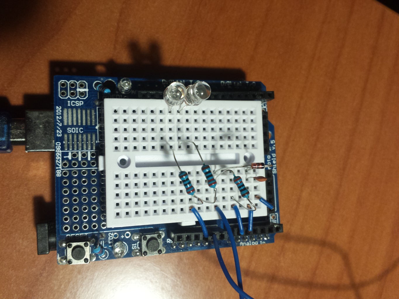
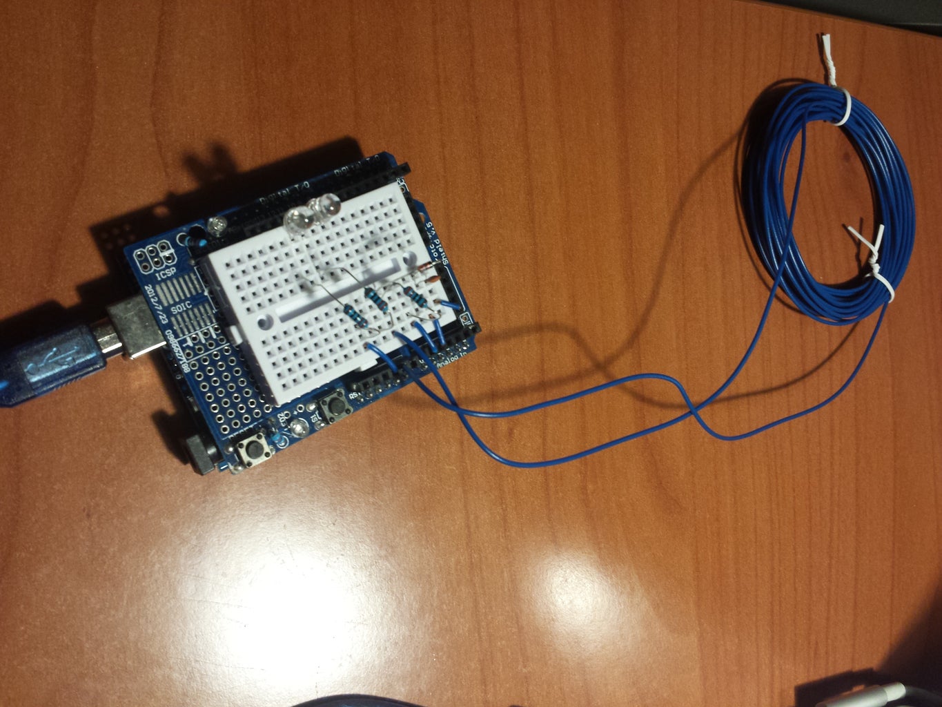

Given the small number of external components, it is perfectly possible to fit the circuitry on the small breadboard of a prototype shield. However, the final result is rather bulky and not very robust. Better is to use an Arduino nano and solder it with the extra components on a 5x7cm prototype board, (see next step)
Only 2 Arduino pins are used for the actual metal detection, one for providing the pulses to the LR filter and one for reading out the voltage on the capacitor. Pulsing can be done from any output pin but the readout must be done with one of the analog pins A0-A5. 3 more pins are used for 2 LEDs and for the sound output.
Here's the recipe:
- On the breadboard, connect the 220Ohm resistor, the diode and the 10nF capacitor in series, with the negative terminal of the diode (the black line) towards the capacitor.
- Connect A0 to resistor (the end not connected to the diode)
- Connect A1 to where the cross-point of the diode and the capacitor
- Connect the non-connected terminal of the capacitor to ground
- Connect one end of the coil to the resistor-diode cross-point
- Connect the other end of the coil to ground
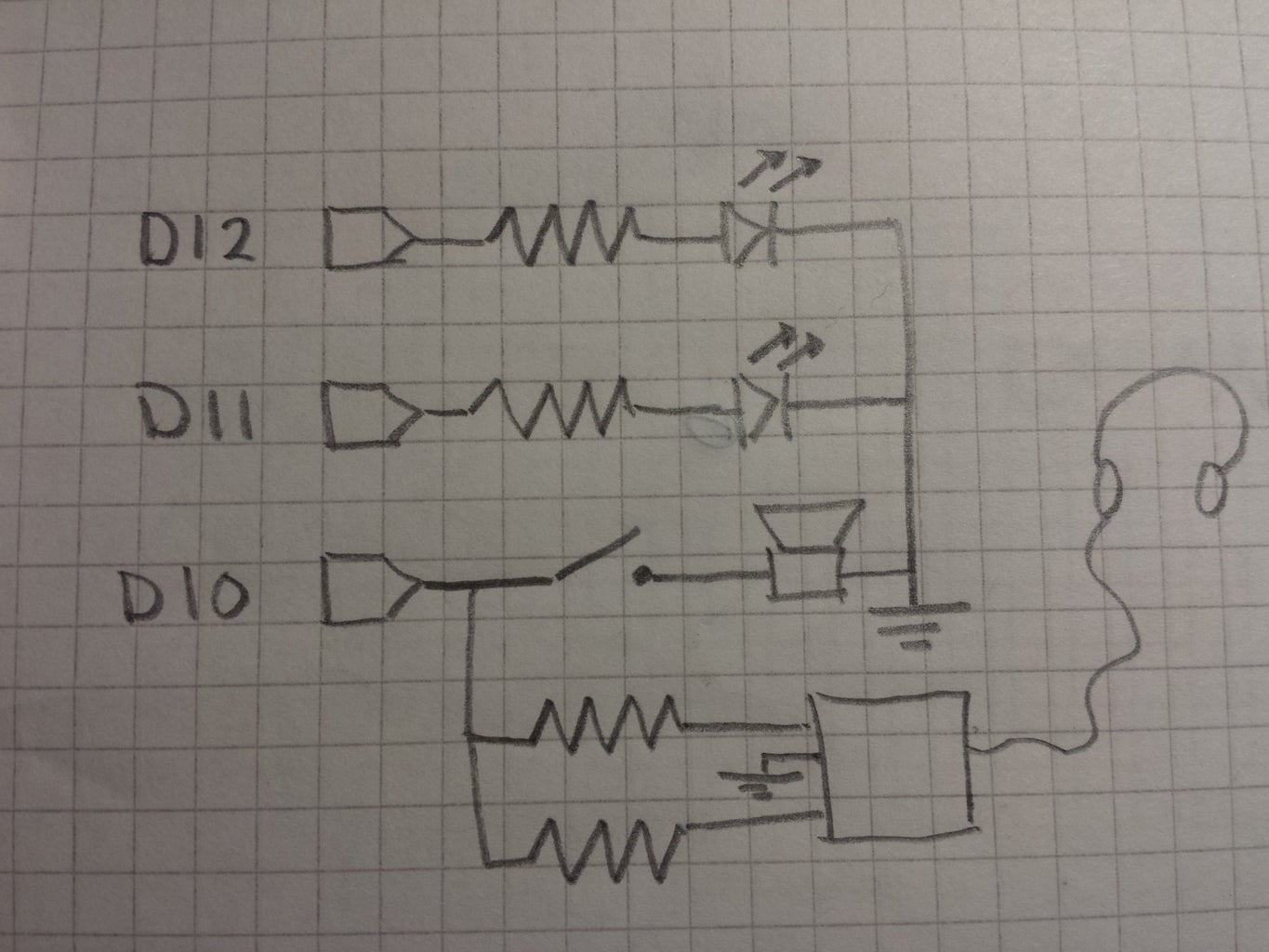
- Connect one LED with its positive terminal to pin D12 and its negative terminal through a 220Ohm resistor to ground
- Connect the other LED with its positive terminal to pin D11 and its negative terminal through a 220Ohm resistor to ground
- Optionally, connect a passive buzzer headphone or speaker between pin 10 and ground. A capacitor or resistor can be added in series to reduce the volume
That's all!
Step 5: A Soldered Version

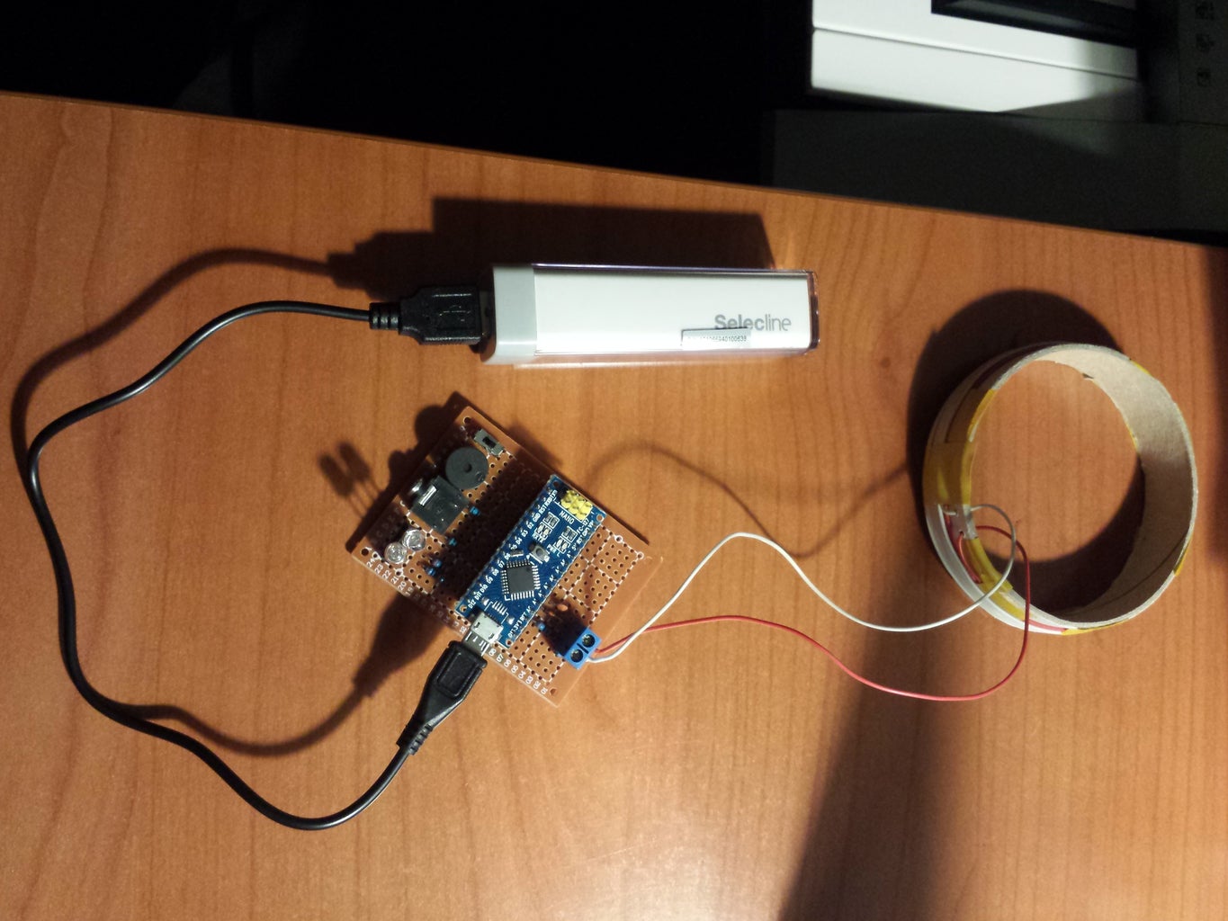
To take the metal detector outside, it will be necessary to solder it. A common 7x5 cm prototype board comfortable fits an Arduino nano and all the required components. Use the same schematics as in the previous step. I found it useful to add a switch in series with the buzzer to turn off the sound when not needed. A screw terminal allows to try out different coils without having to solder. Everything is powered through the 5V supplied to the (mini- or micro-USB) port of the Arduino Nano.
Step 6: The Software
The Arduino sketch used is attached here. Upload and run it. I used Arduino 1.6.12 IDE. It is recommended to run it with debug=true in the beginning, in order to tune the number of pulses per measurement. Best is to have an ADC reading between 200 and 300. Increase or decrease the number of pulses in case your coil gives drastically different readings.
The sketch does some sort of self-calibration. It is sufficient to leave the coil quiet away from metals to make it go quiet. Slow drifts in the inductance will be followed, but sudden large changes will not affect the long-term average.
Attachments

Step 7: Mounting It on a Stick
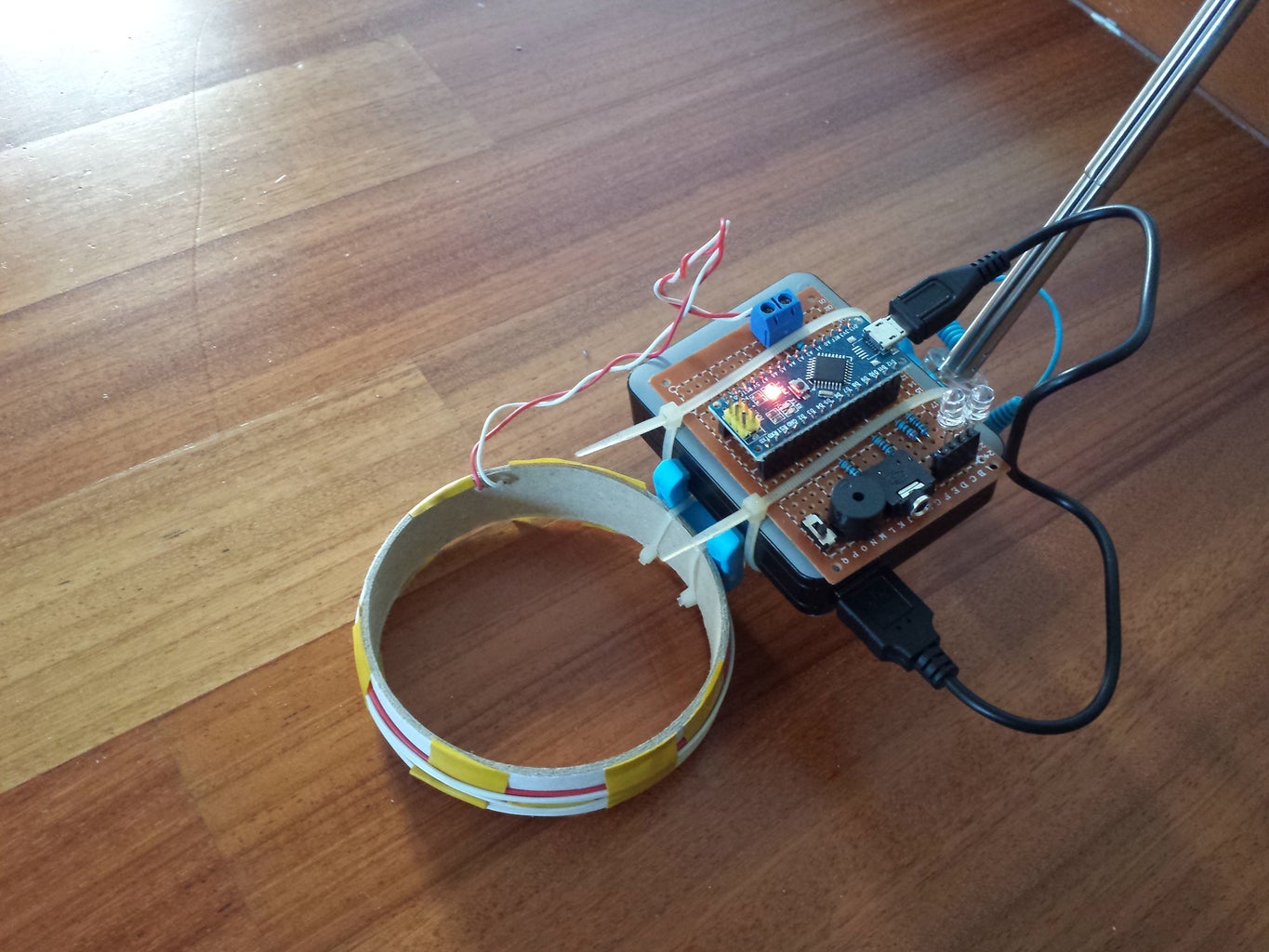

Since you wouldn't want to do your treasure hunts crawling over the floor, the three board, coil and battery should be mounted on the end of a stick. A selfie-stick is ideal for this, since it is light, collapsible and adjustable. My 5000mAh powerbank happened to fit on the selfie stick. The board can then be attached with cable ties or elastics and the coil can similarly be to either the battery or the stick.
Step 8: How to Use It
To establish the reference, it is sufficient to leave the coil ~5s away from metals. Then, when the coil gets close to a metal, the green or blue LED will start flashing and beeps will be produced in the buzzer and/or headphones. Blue flashes and low-pitch beeps indicate the presence of non-ferromagnetic metals. Green flashes and high-pitch beeps indicate the presence of ferromagnetic metals. Beware that when the coil is kept for more than 5 seconds near the metal, it will take that reading as a reference, and start beeping when the detector is taken away from the metal. After a few seconds of beeping in the air, it will turn quiet again. The frequency of the flashes and the beeps indicate the strength of the signal. Happy hunting!

Participated in the
Microcontroller Contest 2017

Participated in the
Sensors Contest 2017


