

Introduction: Solar Energy Management


Some utilities pay generous rates for solar power, some pay about the same as it costs to buy, and some pay little or nothing. If the utility is not paying an attractive rate, it may be better to use up solar energy rather than exporting. Many loads can't be time-shifted, but some can, and examples would be water pumping, heat banks, storing hot (and cold) water, pool pumps, and in the not too distant future, storing energy in battery banks and in electric cars.
One of the problems to solve when switching loads is communication between devices. The solar panels might be on the roof or in a sunny location away from the house, the pumps might be in a pump shed and the energy measurement is in the meter box.
The photo shows some solar panels I put up last year on a homebrew frame. Plug together, attach inverters and start exporting energy. But then I discover that my electricity supplier plans to greatly reduce the amount they are going to pay to the point it makes more sense to use the energy than to export it.
This instructable discusses ways of bringing it all together into a working solution.
Step 1: Measuring Energy

There are lots of ways of measuring high current AC, including some quite sophisticated techniques over at http://openenergymonitor.org/emon/. For my particular application, I was creating and using up to 20kW and this means three phase, and to do it properly this needs three current transformers and three voltage dividers plus an arduino, and doing the sums, it worked out cheaper to buy a commercial three phase meter.
The one photographed above is three phase and flashes a led at 200 pulses per kWh, but it has another very useful feature with an optocoupled output of the same pulse. With two resistors, that pulse can feed into an arduino.
The circuit is 5V to a 10k resistor to the +ve of the optocoupler, and the -ve of the optocoupler to 100k and then to ground. The high side of the 100k resistor goes to pin D2 on an arduino and this can be sampled with an interrupt.
attachInterrupt(0, onPulse, FALLING); // KWH interrupt attached to IRQ 1 = pin2
and then
void onPulse() {}
Next, this pulse width can be measured and turned into a voltage. The full code is in an attached zip file, and has a few other tweaks such as discarding very short pulses.
The arduino can then output a voltage proportional to the AC power. For energy up to 5kW, it can be scaled 1V is 1kW. In my case I measured up to 20kW and so also added a 4x non inverting amplifier with a CA3140 op amp, and then used a little step up module from ebay to generate a 25V supply, and a voltage module to display 0-20V. The display is more eye candy though - an old fashioned solution would be to us an analog 5V meter but relabel it.
Another little tweak was that the arduino outputs a pulse width modulated output, and if you sample this too fast it doesn't give the correct values, so the output goes through a low pass filter and then a voltage buffer to give a true smoothed and buffered 0-5V output.
Step 2: Display the Power ... and Send This Information Somewhere


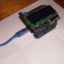
The lower box has an arduino inside it and is taking the pulse and displaying a voltage.
The box on top also is an arduino and this is a two way wireless link that transmits voltages. Put 0-5V in one end, and 0-5V appears at the other end, maybe a kilometer away. And it works both ways too, and if you like you can have multiple channels. I'm only sending that data one way and I ended up with this rather simple solution after getting somewhat sidetracked with wireless mesh algorithms and wireless data protocols. In the end, voltages are easier to work with - you can build a couple of boxes, set them up and not worry any more about wireless protocols.
Code is in a zip at the end.
Attached is a schematic which shows several different wireless modules. There is the NRF24 for short range, the APC220 for medium range and I am using some Yishi long range modules as this goes nearly 1km through trees. There are lots of good writeups using the NRF and the APC modules. The APC module is a generic serial module and there are many brands of these available. Some talk TTL and some use RS232 voltage levels. The schematic is a generic solution for all these, but by far the most practical solution around a house would be NRF24 modules.
I put some little voltmeters in the box - these are so cheap nowadays and they are very useful for debugging. When I first was testing this, I simply looped the voltage back from the output to the input and moved a pot and watched the volts come back a few seconds later.
Step 3: Long Range Data Communication

Long range needs height, and this is a little antenna truss made of aluminium poles and pop-rivetted together. The antenna at the top is 2.4Ghz for a wifi connection using routers configured as repeaters. I used ones by TP-LINK and when you boot them up the menu option is either router or repeater and it was only a couple of easy steps to setup.
The other antenna is 433Mhz and this is a common frequency for modules like the APC220.
A little trap for beginners like me - the 3m cable for radio modules uses standard SMA connections http://en.wikipedia.org/wiki/SMA_connector. However, the 3m cable for a wifi uses RP (reverse polarity) SMA connectors. It can get very confusing if trying to mix and match and it is much easier to keep RP for wifi, and standard polarity for modules, and just buy cables with male on one end and female on the other.
Step 4: Turning Things on and Off


I have drawers full of relays, but relay modules are now available sometimes for almost less than a relay, and make connecting to arduino very easy. Some turn on with a High signal and some with a Low signal, so if you add blinkenlights on a front panel, leds need to be anode to 5V, or cathode to 0V.
Inside the box is a big mess-o-wires. Search dupont header cable on ebay. Male to female do most jobs but sometimes female to female and male to male are useful. Arduino protoboards are also very useful, and some come with rows of 5V and 0V headers (both male and female) so things can be plugged together in lots of different ways.
I also picked up some assorted heatshrink packs and put this on every soldered connection - working in a box for a while can cause wires to break at the solder connection and heatshrink prevents this.
I put a 24V transformer in the box and relays switch 24V. In a pump control box there are 24V relays which then drive contactors. This is one way to amplify a tiny arduino signal up to something that can control 10kW with two steps and with isolation all the way.
Step 5: Talking to the Internet

Ok, so we can sense things, and control things and do it over distances up to a kilometre or so. Why not the internet?
In the attached programs are some vb.net examples that show how to upload to xively. You can download data from xively or use xively to produce graphs and process data in other ways.
There is also a little vb.net routine to send an email and a little algorithm to work out when to turn things on and off. In general terms, I figure that if you can measure lots of things and control lots of things, there must be some sort of combination of loads to switch on and off to match the power being produced.
There are also ways to talk to xively directly from an arduino, however I didn't have much luck with this as the modules seemed to latch up after a week. This made debugging very hard, as it was not clear if this was a stack overflow software issue in the ethernet module, or an overheating problem (the chips do run hot), or glitches from things turning off nearby. A possible solution would be to reboot the module from time to time.
There are also wifi modules that are getting cheaper, eg the $4 ESP8266. I've got these talking to the internet and to google, but real world solutions like xively do stretch the memory of an arduino UNO, and there is a bit of string manipulation which can fragment the memory.
So while in theory one could upload data to the internet and download it elsewhere to control a pump, I couldn't get that quite to 100% reliability, and found dedicated 433Mhz networks were a better solution.
I guess overall this is partly about helping the environment and partly about saving money. There are many numbers to calculate with respects to solar systems, but the main one that matters is payback time. Currently this is an approx $10,000 system that has saved $6,000 in the first year so payback time should be under 2 years, and this was with no government subsidies. As an aside, there was also a wind turbine but it failed after one year and looking at the energy it produced it was going to pay for itself in about 200 years, so solar makes a lot more sense economically.
Please let me know if there are any questions or things that need clarifying in more detail.
Cheers, James Moxham


