

Introduction: Technical Drawing and Drafting Primer


When I went to high school, it was a time when shop classes still existed and you could learn some skills essential for your future maker self. It was the worst of times. It was the best of times...I think one of the most important skills to be gotten out of that was learning how to draw and read technical drawings, things like architect plans, blueprints, parts specifications. If you delved further in engineering, that same precision and attention to detail is carried out in things like exploded diagrams, flowcharts and circuit schematics. Being able to do this by hand involves creative thinking and it is what I feel that is missing when you toss someone a CAD (computer aided design) package to do the same task. Sure, CAD is a useful tool but I feel if you do not know the basics of the process behind it you miss the point of being able to design with your own imagination.
Most of our shop teachers were veterans, you know, the curmudgeony type where something was not quite right..I think that it was the missing cigar stogie to chomp on because they wouldn't allow it in school. Anyway, we had one that told of his story of landing a machinist's job because during one job interview he was able to sketch out a dimensioned drawing of a part that was needed to fix a machine that he saw during the tour of the shop. Technical drawings are how you can graphically communicate in detail exactly what you need.
There is a lot more detail to what I am going to show but this ible should be enough to get you started. So whether you are a budding artist just starting to draw cars, treehouses, redecorating your room, or thinking about drawing up plans for the next generation starship, this is for you.
IMHO: They should really bring drafting(draughting) classes back. Common core for makers and STEM/STEAM.
Note: The drawings I will use to illustrate the techniques might take on the form of sketching and not as formalized as using with instruments. There are tons of references and standards which you can look up to see what professionals do. I hope you get the idea and just try.
(updated 9/22/14 to clarify isometric drawing)
Step 1: Basic Tools...


You need pencil and paper. That about does it. The rest is really to make things neat and exact.
Pencils
There are actually other grades of pencils besides the trusty #2. There is a whole range of hardnesses of the pencil lead. HB or harder is good for technical drawing since it produces a crisper line and doesn't smudge as much. Keep them sharp. Now there are mechanical pencils that you can get in various thicknesses and lead hardness.
Erasers
If, if you make a mistake, there are gum erasers, real rubber erasers, composite erasers and cheap erasers. Try them all out to see what doesn't leave streaks and tear up your paper. We used to have a special bag of fine eraser crumbs to dust the drawing with so that the T-square or other implements moving across the drawing would not smudge the pencil lines.
Pens
There are technical drawing pens. I remember my Koh-I-Noor set. These had fine needle nibs that drew exact lines in various size widths. You had to clean them out after use so they would not clog with the fountain pen like ink system. I think markers have evolved to take the place of technical drawing pens.
Paper
Plain paper is anything you can write on, the back of an envelope, reused scrap from the copy machine, napkin, toilet paper... I am going to use graph paper so what I am drawing might be a little clearer to you. Real architect's vellum is expensive. It is pretty neat stuff. Go to the art or craft store to feel up all the different types of quality paper. You will appreciate a good paper once you use it.
Ruler or straightedge
You can start out with a basic school ruler or get an architectural scale, 3 straightedges joined lenghtwise at the core for one handy instrument marked for different scale measures.
Triangles
I actually found a pack of protractors and triangles at the thrift store. The common angles used in drafting are made into the 45 - 45 - 90 degree triangle and the 30 - 60 - 90 right triangle. Those two triangles are very useful as you will see later. They come in big and small sizes for ease of use on the size of the drawing area.
Compass or Dividers
You need one with a pencil attached to one side for drawing circles or perfect arcs. Dividers are what we know as compasses with points at both leg tips to be used for scribing or as an accurate tool to transfer measurements.
The following are nice things to have to improve the accuracy of your drawing but you learn to do without or improvise when out in the field.
T-square and drawing board
A T-square is just a straightedge with a perpendicular piece at one end that rides along a straight object edge like that of a drawing board or the side of your tabletop. This tool makes it easy for your to draw parallel horizontal or vertical lines depending on where you hook the end of the T-square. Due to a lack of space and portability, we can improvise by lining up one of our triangles along the page edge or lines to act as the T-square.
Drafting tape
If you are using a T-square and drawing board setup, you need a high tack/low residue thin tape like masking tape to fix your drawing paper in one position so it does not shift to ensure that all the lines drawn with the T-square are lined up and parallel.
For other fancy tools, actually go to the office supply store and browse their professional artists section.
French curves
These are various curved plastic pieces. You try to match points on the curved line from your diagram and trace the curve shape that fits to smooth out the line. In computer drawing programs, you usually specify the endpoints of a curved line and manipulate the Bezier's curve to fit between them.
Templates
There are various circle guides or pre-cut shapes available. There may be other industry specific plastic or metal templates like for human ergonomics or fashion design. These speed up the drawing of common symbols or shapes.
Step 2: One Step at a Time...


Starting out...
A technical drawing is the roadmap for your design.
It should have a legend box with gives some basic information like it's title, revision or plan number, owner, special notes, etc.
Your drawing can have a border to define the drawing space and can be on any standard sized paper.
I am going to just make a border the width of my ruler and make a legend box that I will fill in later.
This is our blank slate.
Now, down to business...
Can you visualize something in a glass box? Yup, that teacher said "Some people can't see sh*t in space" but I don't recall anyone failing that class so anyone can do this.
What you see when you look at a face of the glass box is called a view. This is our front view. Orthographic projections are taking what we see on a 3 dimensional object and then putting that on a flat sheet of paper.
Looking down at the top is the top view or plan view and the side is the side view.
Now unfold the glass box with the edges neatly attached and aligned is the overall view.
The object can be oriented in any manner but usually the biggest or best view is the main or front view.
Our glass box has created our reference planes for the three directions x, y and z axes.
Now you see why you should be paying attention in geometry class?
In this ordered world, most of the lines are parallel to each other when they are horizontal going left to right.
If they are going up and down, they are perpendicular to the horizontal lines and forming a perfect 90 degrees or right angle where the lines intersect.
Now unfold the glass box with the edges neatly attached and aligned is the overall view.
Notice how all the lines or edges match up with each other.
We can use the straightedges, T-square and triangles to line everything up.
Transfer all of the measurements exactly from the object to your paper and draw the object views.
We put a gap between the front, top and side views for clarity and to leave room for annotations like measurements.
Step 3: Isometric View...


This is one of the projections we can create that shows the object better with a 3 dimensional look. There is something magic and aesthetically pleasing about looking at an object on an angle.
If we just extend all the intersection points to determine our 3 dimensional shape, we end up with a drawing that is mathematically correct as we map it in space but it foreshortens lines that go off in the distance. Since we want to be able to measure directly off of an engineering drawing, if we use actual measurements for the face of the x, y, z axis, and the view was such that lines go off the horizontal at 30 degrees, a reasonably accurate 3 dimensional object can be drawn. Other angles can be used but 30 degrees seems to provide results that are least distorted.
Use your 30 degree triangle to project a placement guideline from the bottom right corner of your front view. (ignore the other light guidelines drawn in the images) This is just to position the isometric view on the drawing and to judge if it will interfere with the other views already drawn. This is also the z axis of your isometric view.
Pick your starting point for the corner of your object. Create your starting x and y axis there.
Measure using your plans and mark off accordingly for each line on the axes.
You can then map all of the intersection points that form your shape. Your object is "enclosed" in the glass cube or rectangle. Plot the intersection points on each of the faces of the glass box. Use your triangle to project the points marked on each face into the box. Where the lines intersect are your points in 3D space.
Step 4: Size It Up...


Now let's add dimensions to this so whoever reads these plans can duplicate or know how big our object is.
Scaling
Look to what is stated in the legend to determine what scale the drawing is just like we see on a map. This is the proportionate measure that 1 inch on the drawing represents say, one foot or whatever. This drawing scale tells us 3/8th of an inch or one box on the grid represents one foot in real life. You might also see some ratios like 1:60. Whatever you measure off the plans is 1/60th the size in real life. There are some common modeling scale ratios and it really depends on what you want to fit on the paper. Of course, trying to fit the Empire State Building on a regular sheet of paper would require it to be scaled down a lot. Learn your metric measurements which are easier to scale rather than having to convert decimal or fractional inches/feet. By the way, common US door measurements are done by feet - inches. If you are looking for a 36 inch wide door, find a 3 - 0 sized door. A 32 inch wide door is expressed as a 2 - 8 door, and so on. Don't get me started on pipe measurements...
There is a whole style to doing dimension lines but the essence is to lay them out or group so they are not confusing to correctly identify what it is a dimension of. Write the numbers as if you were reading them looking head on, meaning numbers on the side should be numbers written sideways.
Lettering by hand gives each character some character but it goes back to being neat and concise just like you learned to write in kindergarten. Practice and develop your own style or font. If you go to med school, they must have a course in how to write illegibly.
You will notice there is also a range of styles for arrow points and bullet symbols.
The next object drawn is a little more complicated. It really just builds upon the basics. You have a bunch of primitives(basic shapes or objects like cubes, rectangles, spheres, solids.etc...) that are stacked or connected to each other. It just means more points to measure or transfer.
Note that hidden lines are drawn with a dashed line to make it "invisible" or not actually seen in the face of the object.
Dimensioning lines can get a little more complicated but see how they are grouped for clarity and style.
Step 5: Cool Looking Things...


The compass is a wonderful tool for making exact circles or arcs.
Here we have a conical object with a centerline through it. Long line segment, dash, long line segment...
You will usually find this on symmetrical objects such as aircraft and we can just draw one representative side or section. You would then note the section as "typ." or typical. That same section applies throughout.
You might see the CG or center of gravity symbol, the one that looks like the BMW auto logo.
Note that in our isometric projection of the circle, it becomes oblong. You can form that ellipse shape by connecting several marked points off the grid or with a french curve to fit. I sketched the curve.
Step 6: Reach Out and Touch It...

To make the drawings clearer in what materials they represent, you can use various texture fills and patterns. You only have black and white to work with or in the case of blueprints, dark and light.
We can come up with fill patterns that look like wood grain, sand texture, glass, metal and various crosshatch or line patterns. Different shades can be represented by more or less dense fills of lines.
Cutaways or sections cut out are marked by matching sets of letters or numbers.
To get really fancy, we can have "exploded views". These drawings detail how things fit together and are good for assembly instructions or user manuals.
Step 7: It Comes Down to Maths...


This whole thing about accurate drawing and representation is all based on math and geometry.
Here are a few tricks to use in drawing. They were probably discovered before trigonometry was developed to explain why they work. Mostly ideas about parallel lines, intersecting lines, relationship of angles, circles and so forth. It is practically applied in everyday construction tasks like woodworking.
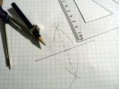
Bisecting a line or finding the exact center
Set the compass at more than the midpoint.
Strike large arcs from both endpoints.
Connect the intersection of the arcs or draw a perpendicular from the line to one of the intersecting points on the arcs.
That is the exact center of the line.
Finding the center of a square
Draw diagonals from each corner.
The intersection is the exact center of the square. This method works for rectangles too.
Note that 3 - 4 - 5 are the measurements of a right triangle, one that has 90 degrees as the corner angle.
Dividing a line segment into a number of equal pieces
Know how many line segments you want to divide your original line into.
Measure equal amounts or multiple units on a line connected to one of the endpoints. Here, we want to divide into 6 pieces so we just mark off 6 units on the new line from our ruler or measure.
Connect the endpoints to form a triangle.
Draw parallel lines based on the bottom of the triangle at each tick mark.
They will intersect the original line at points dividing each of the equal segments.
Step 8: The Reproductive Process...


No, not birds and bees. Learn that on the street like everyone did...wait.
Long before there were interns and copy machines, computers and printers, there was no good way to reproduce a set of plans except by hand.
Then they developed a chemical process for blueprints.
With the advent of computers, they were able to reproduce a set of plans on large scale plotters, inkjet printers and now laser printers.
So what do we do if we want an even better look or stage your product in its natural setting? We can draw in perspective. This renders it into a more realistic image.
The way you see things in real life, parts of objects that are closer to you seem bigger than those further back. This is foreshortening. There is a reference plane that we call the horizon line. Parallel lines like railroad tracks seem to come together and converge on a vanishing point. We can have a single vanishing point in the distance based on the direction we are looking. For objects that are not parallel or perpendicular to our vantage point, we have two vanishing points. Depending on our angle of view to the object, we can shift the vanishing points on our drawing to reflect that perspective.
Perspective drawings can be further enhanced with color and shading. We can even generate shadows based on where we have imagine the light source.
So grab a pencil and paper and start drawing. Make a measured drawing of a nut or bolt, screw threads are fun to draw, tools, anything in the room... Before you know it, you can design cars, houses, K'nex, robots, rocketships...
Young makers, post one of your technical drawings in the comments below. I have a bunch of 3 month pro memberships to give away for your effort. Good luck.

Participated in the
Tech Contest

Participated in the
Teach It! Contest Sponsored by Dremel


