

Introduction: Temperature/Humidity Sensor + Arduino + LabVIEW Data Acquisition


This tutorial will explain step-by-step on how to set up your SHT15 (temperature/humidity) sensor for data acquisition using Arduino. The tutorial further explains how LabVIEW will be used to collect the sensed data to provide numerical and graphic representation.
What you will need:
- SHT15 Breakout
- Arduino Uno
- Arduino software
- LabVIEW software
- Soldering Iron
- Jumper Cables
- Serial Cable
- 1 X 4 Dip Pin
Step 1: Solder Pins to Board


Solder the 1 x 4 Dip Pin to the SHT15 Breakout.
Step 2: Load SHT15 Code Onto Arduino

DOWNLOAD Arduino source code for SHT15 sensor.
Make sure your Arduino is connected to your computer.
OPEN and UPLOAD the Arduino code onto the Arduino.
Make sure you have the Arduino program installed on your computer. If
you have not done so, the program can be downloaded from here: Arduino Software
Attachments

Step 3: Wiring the Sensor to the Arduino
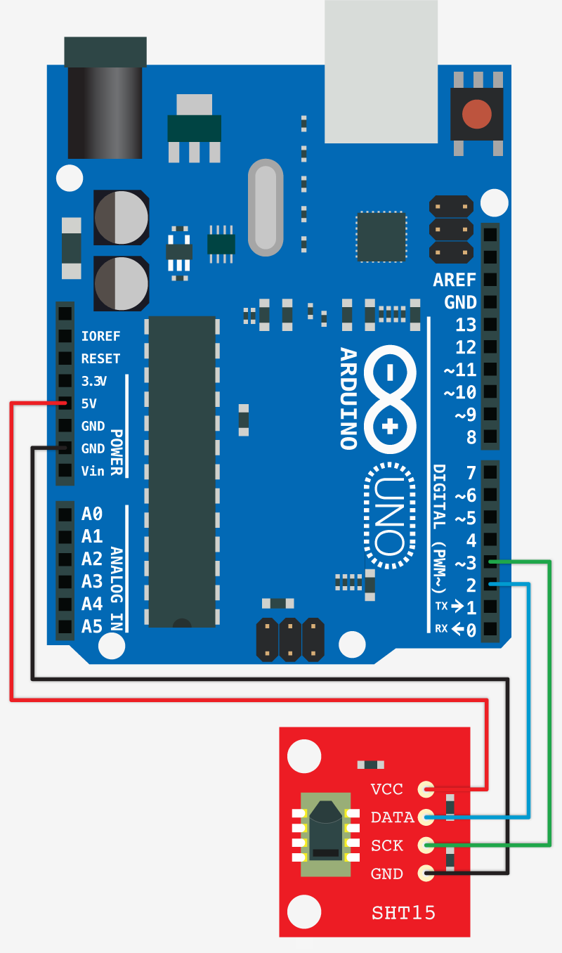
Using jumper wires, connect the following pins (from SHT15 sensor to Arduino):
VCC pin to Pin 5V (Arduino)
DATA pin to Pin 2 (Arduino)
SCK pin to Pin 3 (Arduino)
GND pin to Pin GND (Arduino)
Rule of thumb:
Use different colored jumper cables for each pin:
Red jumper cable used for source
Black jumper cable used for ground
Step 4: Download Sensor VI for LabVIEW

Be sure you have the LabVIEW software installed on your computer.
DOWNLOAD the LabVIEW VI file for the sensor.
OPEN the SHT15 VI file in LabVIEW.
Select the corresponding COM port under the I/O drop-down menu. If there is no port present, select "Refresh" from the menu and the COM port should be apparent to click.
Attachments
Step 5: Run LabVIEW

Now that the SHT15 sensor's VI is open and the sensor is connected, RUN the VI program.
Values should be seen. The waveform graph will show continuous acquisition of data values
Step 6: Setting Up the Thresholds

If the VI is still running, be sure to stop the program in order to make changes to the VI.
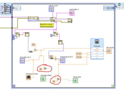
Under the WINDOW menu, select SHOW BLOCK DIAGRAM.
The Block Diagram window will appear. The value of the constants connected to its corresponding comparator (i.e. "greater than or equal to") can be changed.
There are two comparator values that can be changed: Temperature & Humidity
Adjust the constant to any value. If the sensed values from the sensor is greater than or equal to the defined constant, the LED will turn on.


