

Introduction: Throbbing/Fading/Flashing LED With 555 Timer


This tiny circuit is a simple way to make a fading led without having to program chips or writing code. Just a few simple components and you're ready to fade all day.
The end result is a constant fade up and fade down just like a Mac on standby.
Try it! See how small you can build it.
If you like it rate my Instructable. If you don't, rate my Instructable.
Step 1: Gather Tool and Components


For this project you will need:
Electrical Components
470 ohm resistor (or a resistor to drop the current for your desired led from around 8 volts.)
33k resistor ( or a 100k potentiometer for adjustable fade times)
LED ( I used Blue)
100uf Capacitor
555 Timer
Generic NPN Transistor
Copper clad board. breadboard, or project board.
Tools
Dremel or other rotary tool for drilling
1/32" drill bit for wires
Cutting wheel or tin snips if necessary to trim board down
Soldering iron
Scotchbrite pad or fine sandpaper. ( I used sandpaper because it happened to be there)
Muriatic Acid (concrete cleaner or pool chemical) Home Depot and other hardware stores have it.
Hydrogen Peroxide (standard wound cleaner) Found in drugstores, grocery stores, you probably have some at home.
Misc
Latex or Nitrile Gloves
Acetone to clean ink off of board after etch.
Outdoors area to etch in
Plastic or glass container to put etchants in.
Helping Hands clamp with magnifying glass (nice to have a third hand)
I've included the files for Express PCB software. Free download.

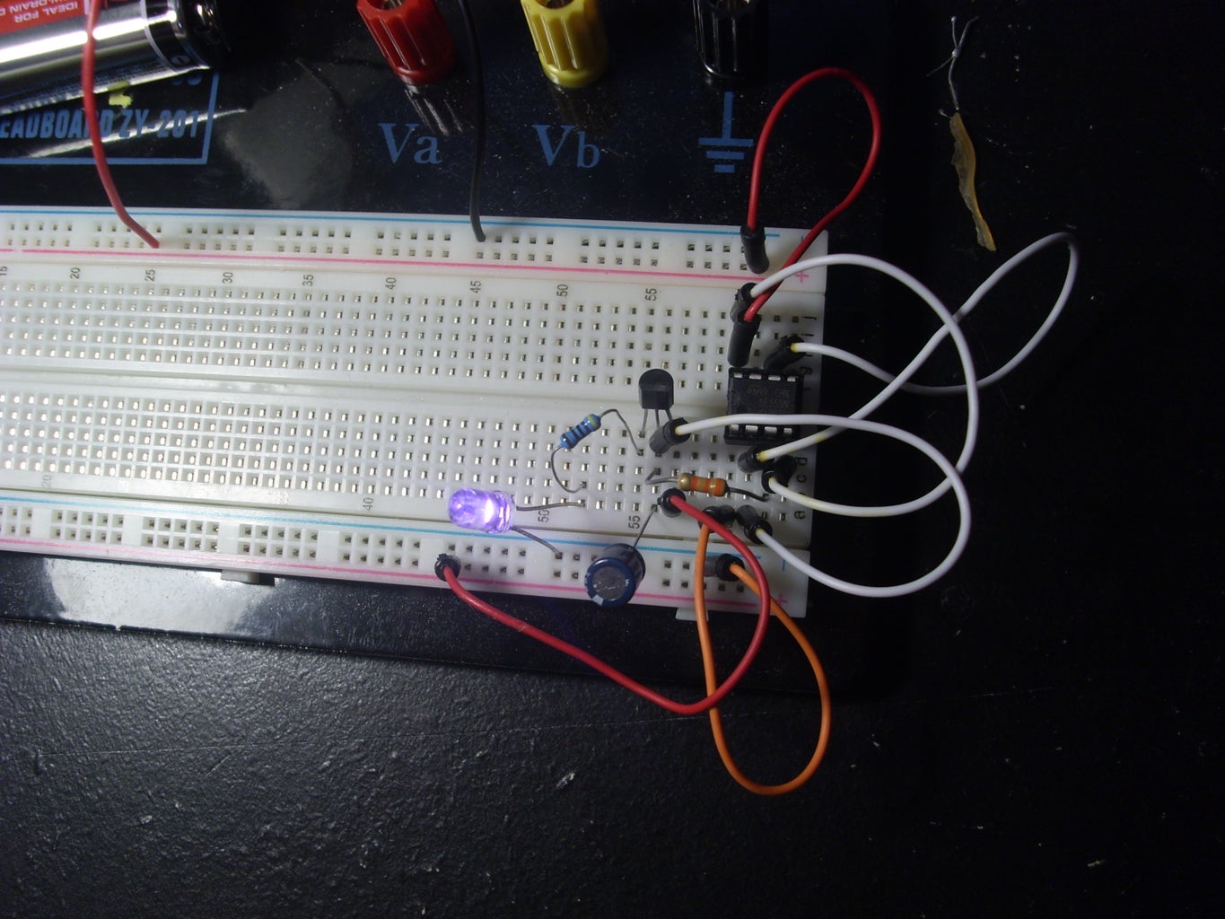
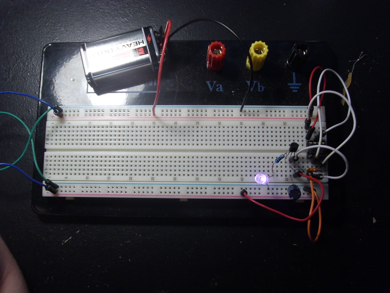
Step 2: Breadboard It
Break out the breadboard and proto it up.
555 Timer
Pin 1- To Ground
Pin 2- Jumper to Pin 6, Jumper to Base of NPN
Pin 3- 33k resistor to base of NPN
Pin 4- Jumper to Pin 8
Pin 5- NC
Pin 6-Jumper to Pin 2
Pin 7-NC
Pin 8-Jumper to Pin 4, Connected to Positive voltage
Emitter of NPN to 470ohm resistor to LED
Base of NPN to + side of cap, then ground - side
Collector of NPN to + voltage
Step 3: Getting Started


For these boards, I took my schematic and predrilled the pcb before I drew the traces. This gave me a little more flexibility when drawing. It works well for one sided board but once you start the two sided boards, it can cause problems.
I used a dremel and a 1/32" bit and hand drilled them. As long as you're careful and make sure you aren't driling at an angle, you can hand drill your holes contrary to popular belief.
I knew I'd be making more of these so I took an old broken jewel case from a CD and used it as a drilling template.
Once you have the schematic and your traces routed, transfer or draw it on the board. I used the drawing method due to the simplicity of the circuit. For a more complex circuit or for a more streamlined process, you might look into the toner transfer method. Anything you draw on the copper will not be dissolved by the acid. I drew the traces and then filled all of the "dead space" with more ink. This was to speed up the etching process. The more copper you're etching, the longer the etch takes.
Once you're all inked up, step outside with our acid and our peroxide.
Step 4: Let's Get Etching


Now that you've got your schematic inked and your Muriatic Acid and Peroxide, let's mix our etching agent. Get yourself a hard plastic container to pour these chemicals in. I like to use a container that is about the size of the board I'm etching to cut down on necessary etchant.
Grab some gloves and put them on or risk chemical burns. I've splashed it on myself and it does burn.
Mix around two parts peroxide to one part acid into your container. Always add the acid to the peroxide and pour the acid down the side of the container instead of splashing it into the middle. This should cut down/eliminate splashing. Drop the board in and lightly agitate the fluid around the board by swirling it. This step is not necessary but it will cut down on etching time. This particular etch took less than two minutes. The container will get hot so be very careful. Grab yourself a plastic fork to manipulate the board and a small container of water to dunk the finished board in upon completion.
Step 5: Clean Up the Etched Board


Grab your acetone, rubbing alcohol, or other ink cleaner and get rid of all the marker. I dropped my board into a small container with a bit of acetone and swirled it around. The marker just floated off. Retreive the board, dry it off, and we're ready to start the electronic side of it.
At this point you can resand/scrub the board if you want to clean it further and bring back that shine. It will oxidize again so don't spend too much time on it.
Step 6: Let's Solder


At this point, you might want to fire up the soldering iron and get your components out.
We need:
The 100uf Capacitor
Blue LED
33k Resistor
470 ohm Resistor
555 Timer
NPN Transistor (PNP will not work)
Our freshly etched board
The rest is easy. Place components making sure to keep polarity in mind. The top left pin with the circle next to it is pin one on the 555 timer. Both the capacitor and the LED have one long lead and one short lead. The long lead is the annode which is the positive side and the cathode is the shorter side.
Push the leads through the holes and bend them slightly on the other side to prevent them from falling out.
Solder away and power it up.
Wait... I forgot to add hole for power wires.
Actually I just forgot to drill them.
Hook up your 9v battery and apply positive to pin 8 and negative to pin 1. After a few seconds the LED should fade up, hold, and then fade back down. Lather, rinse, repeat.
http://www.youtube.com/watch?v=o9f3BoPnGu0
Step 7: Done

You can solder on the wires for a battery terminal and connect as you please.
Or add a switch and turn it on at your discretion.
Check out a short vid here.
http://www.youtube.com/watch?v=o9f3BoPnGu0
I'll try to get a schematic up soon.
Props to this instructable
https://www.instructables.com/id/Beating_LED_Heart_Picture_Frame
Same basic schematic, different implementation.
Enjoy and thanks for reading.
Participated in the
Pocket-Sized Contest


