

Introduction: VU METER (Music Visualizer) #1 With Arduino
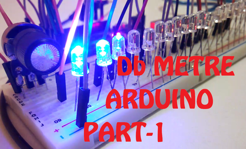


This is the part one of the music visualizer series and In the following tutorial we are going to make a music visualizer AKA the volume meter or the uv meter from an arduino mega . The build process is very simple and easy and the program of arduino is also not that hard.
Step 1: Watch the Video
Step 2: Parts List


The parts needed for this build are
1.ARDUINO MEGA
2.COPPER DOT PCB
3.BREAD BOARD
4.JUMPER WIRES
5.LED (RED ,BLUE ,GREEN)
6.TOOLS(SOLDERING IRON ,SOLDER WIRE)
7.AUDIO SPLITER WITH A JACK
8.HEADER PINS
Step 3: Testing on Bread Board( 1.LED's and ARDUINO )

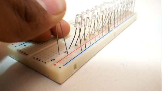


Start by inserting the led on the bread board with the negative leg of the led to a common ground rail of the bread board (led count =20)
the positive leg of the led will be there at any empty rail of the bread board as shown in the video and following pictures
Then connect the ground of the arduino to the common ground rail of the led
Start from the pin 22 of the arduino mega and the flow is shown below
ARDUINO PIN LED COUNT
22------------------------------1
23------------------------------2
24------------------------------3
25------------------------------4
26------------------------------5
: : (pin follows from 22 of the arduino and ending at pin number
: : 41 of the arduino mega)
41-----------------------------20
Step 4: Connecting the Music Source


The music source is the main thing in the following project.
As you have seen in the following video that i have used a audio spliter which will split the aux cable data into two parts one is for our circuit and the other one is which we can connect to the music system\
the connections for audio input follows as
Ground of the aux cable will go to the ground of the arduino.
Left or Right channel of the aux cable will go to the A0 analog input of the arduino mega
Step 5: ADDING THE POTENTIOMETER

The potentiometer is used to increase or decrease the sensitivity of the music VU meter
the connection for the potentiometer are as
1st Pin___________GROUND
2nd Pin___________A1 of arduino
3rd Pin___________+5v or vcc
in the code also we have used the following command lines to the potentiometer to be worked as the sensitivity adjustment
potval=analogRead(A1);
output = analogRead(music);
potval=map (potval,0,1024,5,40);
output = output/potval;
Step 6: UPLOADING THE CODE

After thee construction on the Bread Board we can upload the following code by using the arduino ide
any doubts in the code you can freely ask in the comment section below
Attachments

Step 7: CREATING THE PCB


After a complete test of the following circuit we can construct the same circuit much more stable on the pcb
for that repeat the same process of the connecting the led on the pcb and solder the common ground layer
then connect the audio jack left or right channel and the ground to the A0 and ground
then for the sensitivity use to pot ...
the basic idea you can get from the above video and the rest of the things are how creative you can apply the concept
Step 8: THANKS FOR SUPPORT
you can visit the part 2 of these series click on this link
https://www.instructables.com/id/UV-METER-Part-2-U...
Thanks for visiting the following instructables
If you like the project make sure you give a like
you can visit to my youtube channel and get so many similar projects by clicking the youtube link below

Participated in the
Sensors Contest 2017

Participated in the
Microcontroller Contest 2017


