

Introduction: Use an Accelerometer and Gyroscope With Arduino


More by the author:


About: I post updates on twitter and instagram: @amandaghassaei
I recently bought a combination 3 axis accelerometer and 2 axis gyroscope from Sparkfun and I wanted to post some of the code I used to get it up and running. I'm planning on using it in an Arduino based MIDI controller that I'll be posting soon (video below, code at very bottom of page), I want to use the analog controls from the tilt and rotational movement to control the outgoing MIDI. Accelerometers and gyroscopes are also used frequently on robots for balancing and other types of feedback.
First a bit of basic information:
Gyroscopes measure rotational movement in degrees per second. They will not directly tell you information about tilt, only movement about an axis. Accelerometers measure acceleration, you can easily use this information to calculate the tilt of an object by subtracting the current accelerometer data from a value that you know to be zero tilt.
For this project I used the 5 Degrees of Freedom IDG500/ADXL335 board from Sparkfun. I like this board because it outputs the accelerometer and gyroscope data as 5 analog voltages which can easily be read using five of the Arduino's analog input pins. Some accelerometers and gyroscopes output data digitally by encoding it in a pulse-width modulated (PWM) signal. If you are short on analog input pins on your Arduino, it may be a good idea to use one of these digital chips, but the analog chips are nice because they require minimal effort to get working.
Parts list:
IMU Analog Combo Board - 5 Degrees of Freedom IDG500/ADXL335 Sparkfun SEN-11072
Arduino Uno Sparkfun DEV-11021
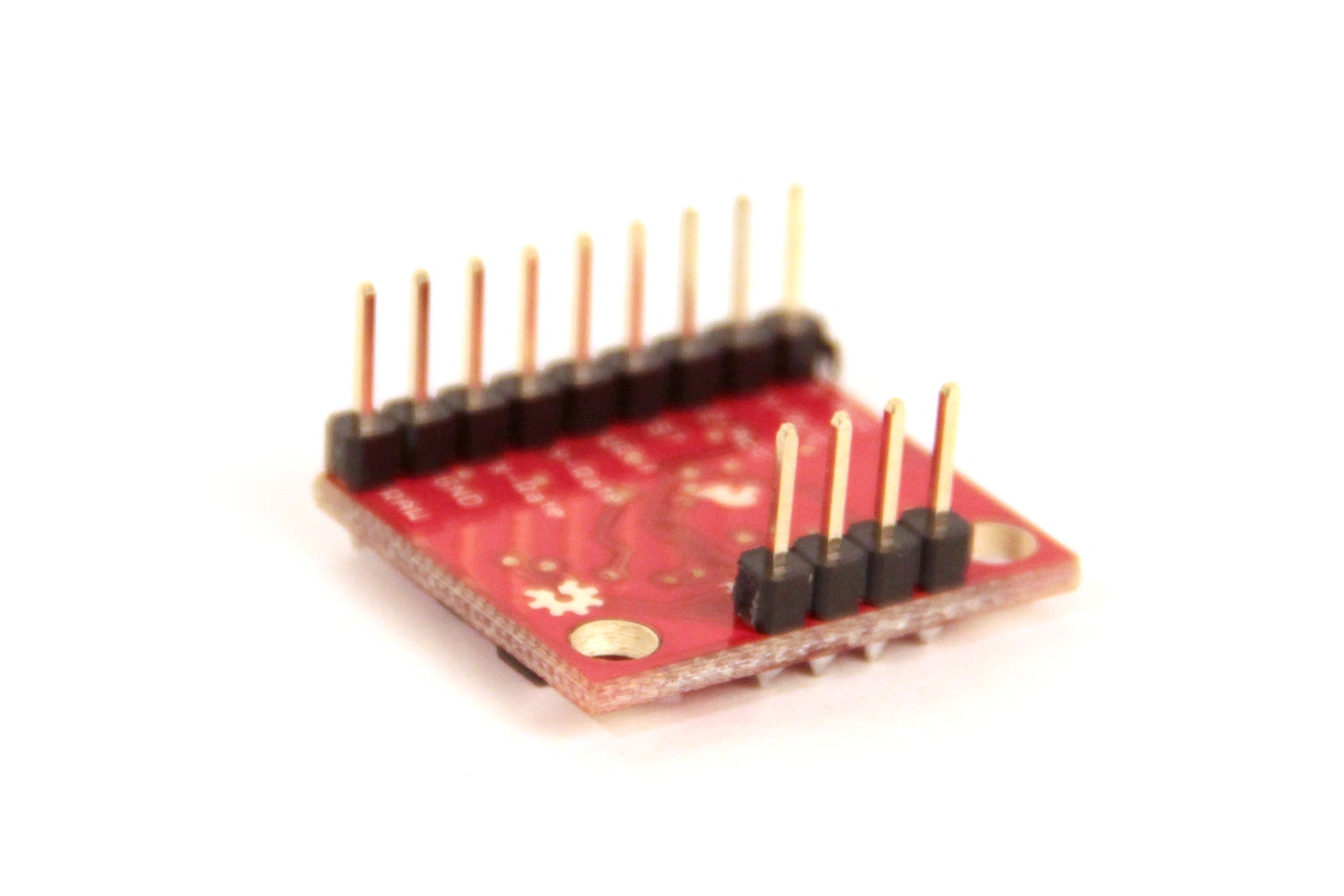
male header pins Sparkfun PRT-00116
22 gauge wire
breadboard
Steps:
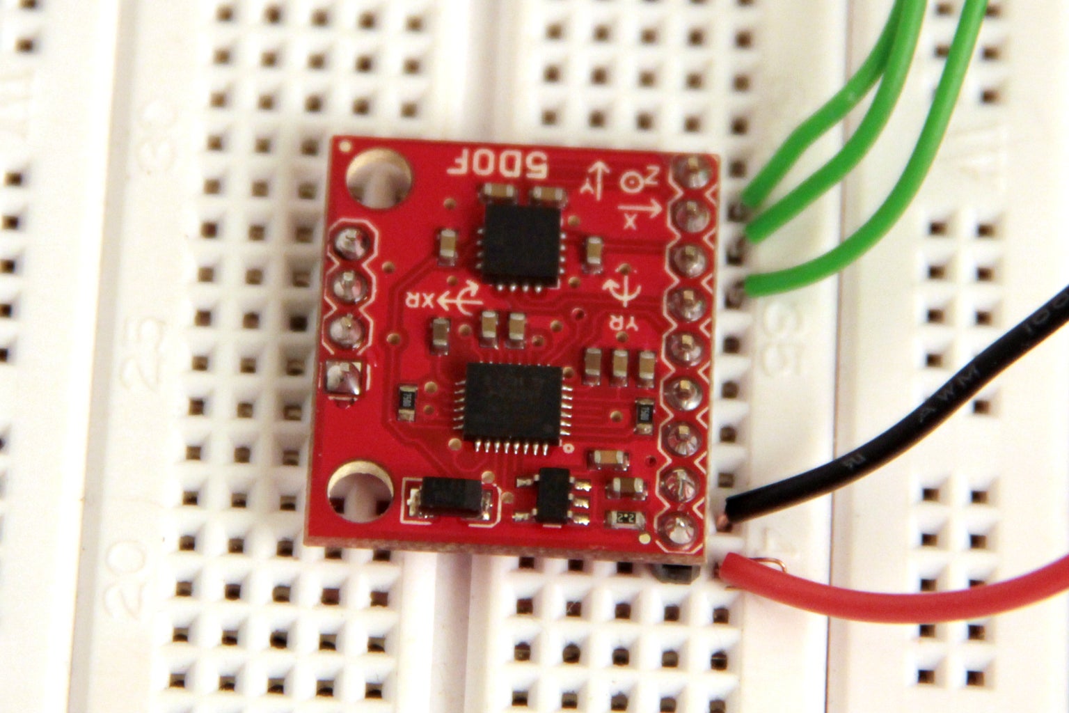
Solder header pins to the accelerometer/gyro board. On a breadboard connect Arduino 5V to "RAW" pin, Arduino ground to ground, then connect the pin labeled X-Acc to A0, Y-Acc to A1, and Z-Acc to A2
The code below will display the X,Y, and Z acceleration fro your board int he serial monitor (ctrl/command + shift + M). I tried to center the values around a zero point by introducing the variable "zero" in my code and then subtracting all my incoming data from this number. This way when the board is held parallel to the ground, the X and Y acceleration both read 0. When the board is tipped to positive X it will display a positive number, and when it is tipped to negative X it will display a negative number (same goes for Y). This accelerometer code allows you to determine the orientation of your board in 3D space.
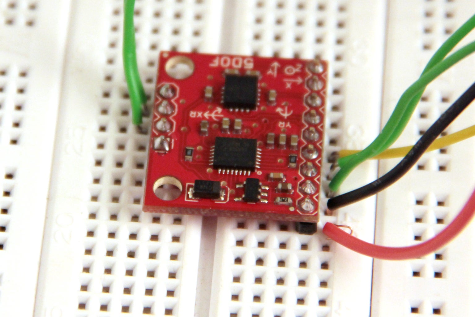
Sometimes you may want to use a gyroscope to get rotational information about your board that cannot be calculated with an accelerometer. On a breadboard connect the pin labeled Vref to A0, yRate to A1, xRate to A2, y4.5 to A3, and x4.5 to A4.
You may be wondering about the difference between the X/YRate and X/Y4.5 outputs. Gyroscopes measure degrees per second, this gyroscope outputs a voltage based on the degrees of movement per second so we can say that it is outputting volts per degrees per second (V/°/s). From the datasheet of the gyroscope we can see that the X/YRate is outputting data with 2.0mV/°/s sensitivity and the X/Y4.5 is outputting data with about 4.5 times the sensitivity, or 9.1mV/°/s.
Upload the following code to display the output from each of these (fig 6).
I wanted to zero this code as I did with the accelerometer code above. I was expecting the outputs from the x and y gyro to equal the output from Vref while the device is held stationary, but as you can see in fig 6, this is not the case (if anyone has an explanation for this I'd love to hear it!). Since Vref was not a god reference for me to zero my output to, I used some preset values based on the data from fig 6, you can find them in my print statements in the code below. I also removed the monitoring of Vref since it appeared to be stable no matter how much I moved the device, this also saved me an analog input pin on the Arduino.
The results from this code are shown in figure 7. Rotation around the x and y axes will change the values of xRate, x4.5, yRate, and y4.5.
I used this accelerometer/gyro in a Arduino-based MIDI controller I've been working on. Below is the code for the two applications I demoed in the video at the top of this instructable. I connected all three axes of the accelerometer and the two 4.5gyro outputs for this project.
single pixel moving around, triggering MIDI (only uses x and y accelerometer):
four pixels bouncing (only uses x accelerometer, uses x gyro to clear pixels):
First a bit of basic information:
Gyroscopes measure rotational movement in degrees per second. They will not directly tell you information about tilt, only movement about an axis. Accelerometers measure acceleration, you can easily use this information to calculate the tilt of an object by subtracting the current accelerometer data from a value that you know to be zero tilt.
For this project I used the 5 Degrees of Freedom IDG500/ADXL335 board from Sparkfun. I like this board because it outputs the accelerometer and gyroscope data as 5 analog voltages which can easily be read using five of the Arduino's analog input pins. Some accelerometers and gyroscopes output data digitally by encoding it in a pulse-width modulated (PWM) signal. If you are short on analog input pins on your Arduino, it may be a good idea to use one of these digital chips, but the analog chips are nice because they require minimal effort to get working.
Parts list:
IMU Analog Combo Board - 5 Degrees of Freedom IDG500/ADXL335 Sparkfun SEN-11072
Arduino Uno Sparkfun DEV-11021
male header pins Sparkfun PRT-00116
22 gauge wire
breadboard
Steps:
Solder header pins to the accelerometer/gyro board. On a breadboard connect Arduino 5V to "RAW" pin, Arduino ground to ground, then connect the pin labeled X-Acc to A0, Y-Acc to A1, and Z-Acc to A2
The code below will display the X,Y, and Z acceleration fro your board int he serial monitor (ctrl/command + shift + M). I tried to center the values around a zero point by introducing the variable "zero" in my code and then subtracting all my incoming data from this number. This way when the board is held parallel to the ground, the X and Y acceleration both read 0. When the board is tipped to positive X it will display a positive number, and when it is tipped to negative X it will display a negative number (same goes for Y). This accelerometer code allows you to determine the orientation of your board in 3D space.
Sometimes you may want to use a gyroscope to get rotational information about your board that cannot be calculated with an accelerometer. On a breadboard connect the pin labeled Vref to A0, yRate to A1, xRate to A2, y4.5 to A3, and x4.5 to A4.
You may be wondering about the difference between the X/YRate and X/Y4.5 outputs. Gyroscopes measure degrees per second, this gyroscope outputs a voltage based on the degrees of movement per second so we can say that it is outputting volts per degrees per second (V/°/s). From the datasheet of the gyroscope we can see that the X/YRate is outputting data with 2.0mV/°/s sensitivity and the X/Y4.5 is outputting data with about 4.5 times the sensitivity, or 9.1mV/°/s.
Upload the following code to display the output from each of these (fig 6).
I wanted to zero this code as I did with the accelerometer code above. I was expecting the outputs from the x and y gyro to equal the output from Vref while the device is held stationary, but as you can see in fig 6, this is not the case (if anyone has an explanation for this I'd love to hear it!). Since Vref was not a god reference for me to zero my output to, I used some preset values based on the data from fig 6, you can find them in my print statements in the code below. I also removed the monitoring of Vref since it appeared to be stable no matter how much I moved the device, this also saved me an analog input pin on the Arduino.
The results from this code are shown in figure 7. Rotation around the x and y axes will change the values of xRate, x4.5, yRate, and y4.5.
I used this accelerometer/gyro in a Arduino-based MIDI controller I've been working on. Below is the code for the two applications I demoed in the video at the top of this instructable. I connected all three axes of the accelerometer and the two 4.5gyro outputs for this project.
single pixel moving around, triggering MIDI (only uses x and y accelerometer):
four pixels bouncing (only uses x accelerometer, uses x gyro to clear pixels):

Participated in the
Hurricane Lasers Contest

![Tim's Mechanical Spider Leg [LU9685-20CU]](https://content.instructables.com/FFB/5R4I/LVKZ6G6R/FFB5R4ILVKZ6G6R.png?auto=webp&crop=1.2%3A1&frame=1&width=306)


