

Introduction: Wi-Fi Smart Scale (with ESP8266, Arduino IDE, Adafruit.io and IFTTT)


If it's already summer where you live, it's probably a great time for outdoor fitness activities. Running, cycling, or jogging are awesome exerciser for you to get in shape.
And if you want to lose or control your current weight, it is essential to keep a record of your results. Using a sportsband (link / link / link) for instance, will allow you to verify whether you are on the right track and stay motivated. But it's essential to keep record of your weight progress. And with the right tools and using a little electronics and programming, you can make your own internet connected bathroom scale! You can find several bluetooth smart scales of different manufactures online (https://rebrand.ly/smartscale-GB, https://rebrand.ly/smartscale-BG and https://rebrand.ly/smartscale-AMZ for instance). But instead of buying one, why not lose some weight by making your own gadget?
In this project I designed a smart bathroom scale, using some 3D printing, an ESP8266, IFTTT and Adafruit.IO. You can use this tutorial to practice several skills: 3d printing and laser cutting skills, soldering, electronics, programming, etc.
On the next steps I'll show you how I 3D printed it, wired the circuits, and made the code. In the end of this tutorial you'll be ready to measure your weight and log it online!
You can find new features in my new tutorial: https://www.instructables.com/id/Wi-Fi-Smart-Scale-with-ESP8266-Arduino-IDE-Adafrui/! This time I added an integrated clock (synchronized with an internet server) and a buzzer. Once the alarm is triggered, it continues to ring until the user can gather enough courage to get out of the bed and stand for a few seconds on the scale. Check it out!
Some of the knowledges used here were based on Becky Stern awesome Internet of Things Class. It's highly recommended!
Liked that project? Please consider supporting my future projects with a small Bitcoin donation! :D BTC Deposit Address: 1FiWFYSjRaL7sLdr5wr6h86QkMA6pQxkXJ
Step 1: Tools and Materials


The following tools and materials were used in this project:
Tools and materials:
- 3D printer (link / link / link). It was used for printing the case where the electronics are encloused.
- Solder iron and wire. Some of the components (ESP8266 Firebeetle and LED matrix cover, for instance) doesn't come with soldered terminals. I needed to solder some wires or pins in order to connect those devices.
- Shrinking tube. l also had to solder the wires of each load cell. A piece of shrinking tube might be used for a better isolation of the conductors.
- Screwdriver. The structure is mounted using some screws. A set of screwdrivers was used.
- Screws. I used some screws to attach the 3D printed parts to the base of the scale.
- M2x6mm Bolts. They were used for mounting the electronics inside the case.
- 1.75mm PLA (link / link / link) of any color you want.
- FireBeetle ESP8266 dev board. It's really easy to use and program using Arduino IDE. It has built-in Wi-Fi module, so you can use it in a variaty of projects. It has a connector for a 3.7V battery, which was really usefull for assembling this project. I has also a built-in battery charger. It will recharge the battery when connected to an USB plug. You can also use other ESP8266 based boards (link / link / link) if you wish. Deppending on the board you choose, it would be a little more difficult to connect and recharge the battery, or to connect the LED matrix. The dimensions of the case will also need to be verified.
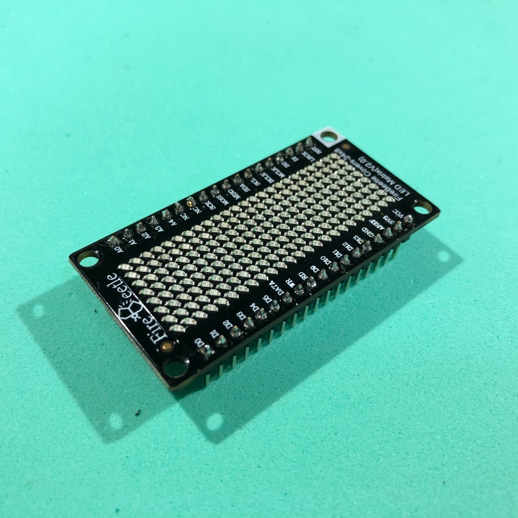
- Firebeetle covers - 24x8 LED matrix. This module easilly fits on top of the Firebeetle ESP8266 dev board. I used it to display the values measured by microcontroller, display some status, etc. You can also use other kinds of display if you wish, like ordinary LCD displays (link / link / link) or OLED displays (link / link / link).
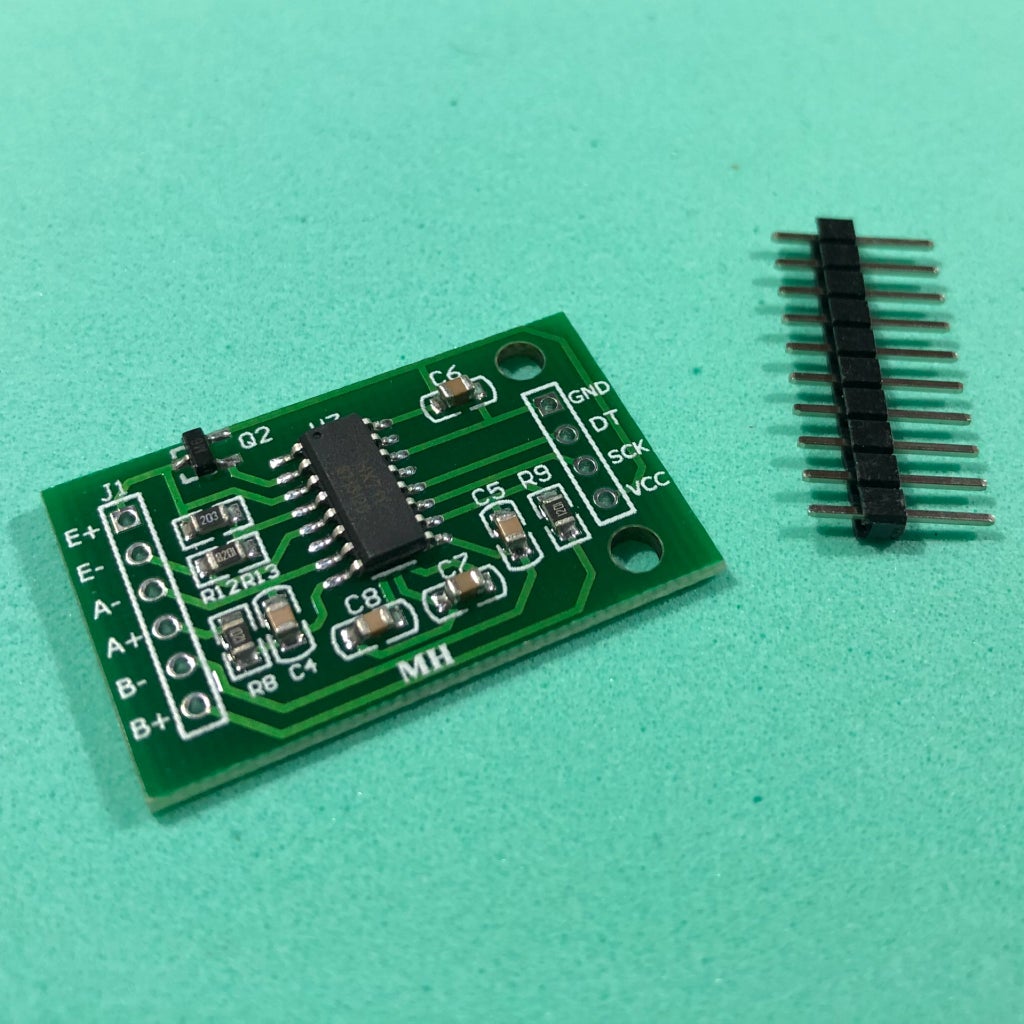
- HX711 module (link / link / link). This works as a load cell amplifier. Four strain gauge load cells are connected to this module, and it communicates on a serial communication with the ESP8266 microcontroller.
- 50kg load cell (x4); (link / link / link). They are used to measure the weight of the user. Four of them were used for a maximum weight of 200kg.
- Micro USB cable;
- 6 female-female jumper wires;
- 2 x 15 mm plywood sheet (30 x 30 cm). It was used for the base of the scale.
The links described above are only a suggestion of where you can find the items used in this tutorial (and support my future hacks). Feel free to search for them elsewhere and buy at your favourite store.
I used a FireBeetle ESP8266 dev board, which was kindly supplied by DFRobot. It worked perfectly! I also tested the code with a NodeMCU board. It also worked fine (although the time for connection was significately longer... I still don't know why...).
Did you know you can buy a Creality Ender 3D printer for only $169.99? Get yours! https://rebrand.ly/3Dprinter-GB
Step 2: 3D Modeling


The smart scale was desgined using Fusion 360 CAD software. The model is composed of three different 3D printed parts: cover, case and foot.
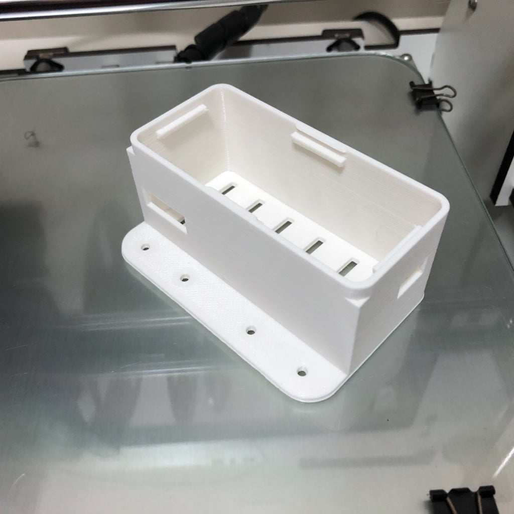
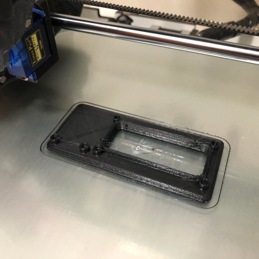
The case provides an enclosure for the electronics, protecting them from physical contact. Electronics are attached in the cover part (using some bolts). This part has a front visor, where the display is fitted. Load cells fit into the foot part, which allows the sensors to be attached to the base.
Step 3: 3D Printing


You can download all the stl files on the following websites:
https://www.thingiverse.com/thing:2934791
https://pinshape.com/items/45555-3d-printed-diy-wi-fi-smart-scale
https://www.youmagine.com/designs/diy-wi-fi-smart-scale
https://cults3d.com/en/3d-model/gadget/diy-wi-fi-smart-scale
https://www.myminifactory.com/object/3d-print-diy-wi-fi-smart-scale-66654
I printed the whole structure in PLA, usign two different colors. The whole print took me around 5h30, using 0.2 mm resolution and 10% infill. No supports needed.
This is a experimental prototype. Notice that it was designed for a given ESP8266 dev board model (the ESP8266 Firebeetle).
If you don't have a 3D printer, here are some things you can do:
- Ask a friend to print it for you;
- Find a hacker/maker space nearby. The parts used in this model can be printed quickly. Some hacker/maker spaces will only charge your for the materials used;
- Buy your own 3D printer. You can find the Creality Ender 3 for only $169.99! Get yours at https://rebrand.ly/3Dprinter-GB
- Improvise! You can try to assemble a structure without 3D printed parts.
Step 4: Woodworking


The base of my scale was mede of two 15mm 30 x 30 cm sheets of plywood.
I made some whole using a screwdriver for passing the wires of the load cells, and for attaching the 3D printed parts.
Step 5: Preparing the Electronics: ESP32 Firebeetle and LED Matrix


Some of the components had to be soldered before their installation on the case.
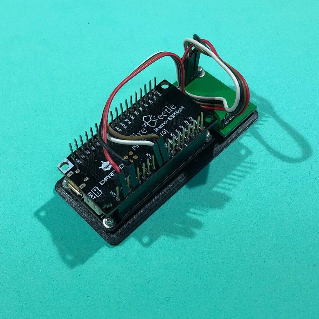
I soldereded a male-female pin bar to the ESP8266 module. This way I could connect the LED matrix shield on its top, on the female connectores, and use the male pins for the connection to the HX-711 module (for the sensors).
I alse had to solder a male pin bar on the LED matrix, so that it could be connected to the ESP8266 module.
Step 6: Preparing the Electronics: HX711 and Load Cells


Solder HX711 terminals
Most HX711 boards come without soldered pins on their terminals. I soldered a male pins bar, which was used later for the connection to the ESP8266 development board and forthe load cells.
Solder load cells signal terminals
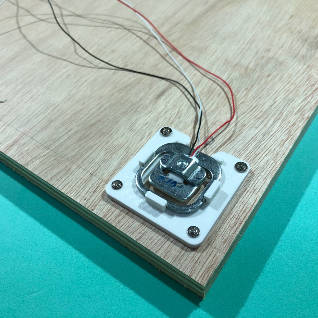
Load cells usualy have three wires (black, white and red). The red wire is the signal one, which I connected to the HX711 module. For that I used two female-female jumpers. I cut one side of the jumper and solder it's wires to the load cell red wire. I used a shrinking tube around the solder for a better isolation.
I also had to solder white and black load cells wires, but it was done only after the sensors were positioned and attached to the structure.
Step 7: Assembling the Scale - Pt1


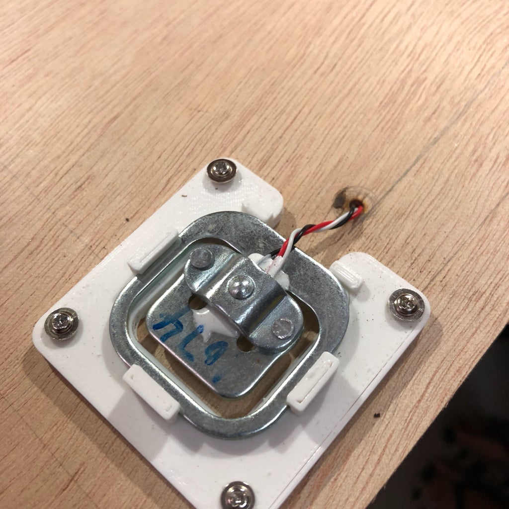
First I had to fit the sensor inside the 3D printed foot parts. They were locked inside this fame, and later attached to the structure using some screws.
I used four M2x1.6mm for attaching the display to the 3D printed cover part. Two more bolts were used for the HX-711 module. The ESP8266 is connected to the display module using a female pin bar. A four-wire jumper connects the HX-711 to the ESP8266 module. More on this on later steps.
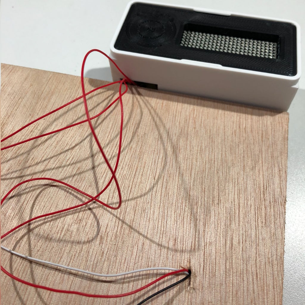
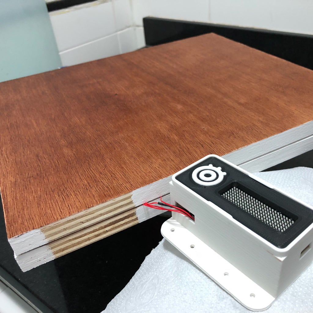
The cover part fits inside the 3D printed case. The case has two other rectangular holes: one for the cables between the HX-711 module and the load sensors, and other for the USB cable used for powering up the circuit and uploading the code. The case was closed only after the connection of the sensors (shown in next step).
Step 8: Assembling the Scale - Pt2


Once 3D printed parts and wood panels were ready, it was time to assemble the structure. The following steps were taken:
1. Installed the load cells on the first wooden pannel. I used for screws for each.
2. A hole was made on the wooden panel right above each sensor. The cables passed through those holes to the other side of the pannel.
3. Soldered the wires according to the image shown in next step.
- Upper left white wire <=> Upper right white wire
- Lower left white wire <=> Lower right white wire
- Upper left black wire <=> Lower left black wire
- Upper right black wire <=> Lower right black wire
Use some shrinking tube to isolate the wires.
4. Attached the 3D printed case. Passed the red wires through one of its holes and connected them to the HX711 module.
5. Installed the second pannel on the top of the first one, using four screws.
Step 9: Final Touches


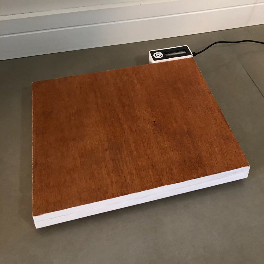

I painted the wooden panels and add some details to the case, for a better finishing.
You might choose different colors or even add a different material to the surface.
Step 10: Wire Up the Circuit


Each device was connected according to the schematics.
HX711 - input:
- Upper left load cell signal (red wire) => HX711 E- pin
- Lower left load cell signal (red wire) => HX711 A+ pin
- Upper right load cell signal (red wire) => HX711 A- pin
- Lower right load cell signal (red wire) => HX711 E+ pin
HX711- output (use a female-female jumper wire):
- HX711 Vcc pin => ESP8266 3.3V pin
- HX711 GND pin => ESP8266 GND pin
- HX711 SCK pin => ESP8266 GPIO 12 (pin D9)
- HX711 DT pin => ESP8266 GPIO 0 (pin D8)
Display module:
- Connect it on the top of the Firebeetle ESP8266
When everything is wired up, close the case, plug a USB cabe on the ESP8266 and get ready for uploading the code.
Step 11: Setup FireBeetle ESP8266 on Arduino IDE

For this project I used Arduino IDE for programming my ESP8266. It's the easier way if you've already used an Arduino before, and you won't need to learn a new programming language, like Python or Lua for instance.
If you've never done this before, first you'll have to add ESP8266 board support to the Arduino software.
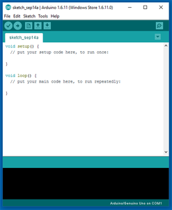
1. Download and install Arduino IDE latest version
You can find the latest version for Windows, Linux or MAC OSX on Arduino's website: https://www.arduino.cc/en/main/software
Download it for free, install it on your computer and launch it.
2. Adding ESP8266 board
Arduino IDE already comes with support to a lot of different boards: Arduino Nano, Mine, Uno, Mega, Yún, etc. Unfortunatly ESP8266 isn't by default among those suported development boards. So in order to upload your codes to a ESP8266 base board, you'll have to add its properties to Arduino's software first.
- Navigate to File > Preferences (Ctrl + , on Windows OS);
- Add the following URL to Additional Boards Manager textbox (the one on the bottom of the Preferences window): https://raw.githubusercontent.com/DFRobot/FireBeetle-ESP8266/master/package_firebeetle8266_index.json
- If the text box wasn't blank, it means had already add other boards before on Arduino IDE before. Add a comma at the end of the previous URL and the one above.
- Hit "Ok" button and close the Preferences Window.
- Navigate for Tools > Board > Boards Manager for adding your adding your Firebeetle ESP8266 board.
- Type "Firebeetle-ESP8266" on the search text box, select "FireBeetle-ESP8266 by DFRobot" and install it.
Now your Arduino IDE will be ready to work with the Firebeetle ESP8266 development board.
3. Adding the libraries
The following libraries will be used for our Arduino code. Download the following libraries:
- Adafruit NeoPixel library (https://github.com/adafruit/Adafruit_NeoPixel)
- Arduino http client library (https://github.com/arduino-libraries/ArduinoHttpClient)
- Arduino IO library (https://github.com/adafruit/Adafruit_IO_Arduino)
- Adafruit MQTT library (https://github.com/adafruit/Adafruit_MQTT_Library)
- HX711 library (https://github.com/bogde/HX711)
- Firebeetle LED matrix library (https://github.com/Chocho2017/FireBeetleLEDMatrix)
Navigate to Sketch -> Include Library -> Manage Libraries... on your Arduino IDE and add the libraries above.
Step 12: Adafruit.IO Configuration


There are a lot of datalogging services available for communicating a microcontroller to the web. With those services you can upload/download data to/from the cloud, and do a lot of cool stuff. Take a look on my tutorial on how to use an Arduino + ESP8266 to send data from a mini-weather station for Thinkgspeak for instance.
Adafruit.IO is one of those free services. It's really easy to use and promises to bring internet of things to everyone!
Create Adafruit IO Web Feed
- Sign in at https://io.adafruit.com/
- Under Feeds >Create a new Feed add a new feed named "my weight". It will create a database, and we will use it store the commands received by the gadget.
Copy your Adafruit.IO key, which will be later used for allowing your device accessing the database. Navigate for Settings > View AIO key and copy the active key code. You'll need it for your Arduino (NodeMCU) code later.
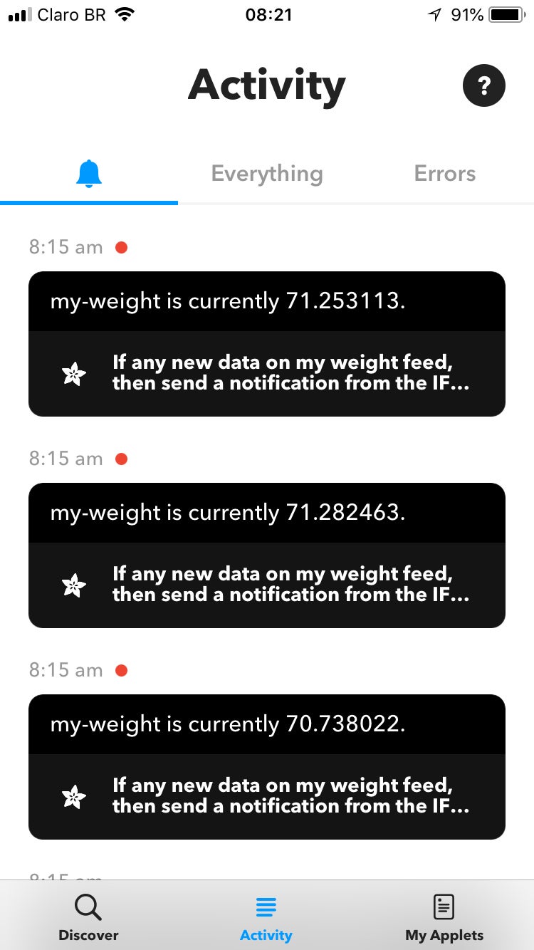
In the next step I will show you how to configure IFTTT, another platform I used in this project. Whenever the NodeMCU measures your weight, it will save this value on Adafruit.IO database. IFTTT platform will then send the value to fitness tracking plaform (Fitbit, Strava, iOS Health or Misfit).
Step 13: IFTTT Configuration


IFTTT is a free platform that helps you connects apps and devices. You can use it to connect your smartphone with other gadgets, or to share data between your favourite webservices (like Google, Facebook, Twitter, Instragram, etc.) and other physical devices, for instance. And the best part is that it's really easy to use!
IFTTT uses a "if this then that" logic, where "this" represents a service that will trigger a given action given by "that". This way you create small applets connecting webservices and devices.
For this project I used IFTTT for pushing the measured weight from Adafruit.io database fot Fitbit.
First you'll have to sign in at:
Then install IFTTT app on your smartphone. You can find it at Google Play Store:
https://play.google.com/store/apps/details?id=com.ifttt.ifttt
You can also find it on Apple store (for iPhone users):
https://itunes.apple.com/us/app/ifttt/id660944635?mt=8
On the website, navigate to New Applet (click the arrow button next to your login to access the menu). I the next step I'll show you how I created my applet.
Step 14: IFTTT Applet - IOS Health


Create the applet on the website:
- Click +This;Type "adafruit" on Seach service text box and select Adafruit.IO > Any new data. As it's described on IFTTT website, it will create a trigger that fires any time there is new data in your feed. Select "my weight" feed;
- Now choose +That;
- Type "ios health" and select iOS Health > Log your weight. This save a new weight measurement to iOS Health. Click add ingredient and select Value.
- Finish your applet and turn it on.
Testing:
- On Adafruit.io, select your feed, Actions > add data;
- Enter your current weight (or any other value). This value will be stored on Adafruit.io database. IFTTT will listen to it and upload it to Fitbit database;
- Log in your Fitbit account an verify if your current weight was updated.
Step 15: IFTTT Applet - Fitbit


Create the applet on the website:
- Click +This;Type "adafruit" on Seach service text box and select Adafruit.IO > Any new data. As it's described on IFTTT website, it will create a trigger that fires any time there is new data in your feed. Select "my weight" feed;
- Now choose +That;
- Type "fitbit" and select Fitbit > Log your weight. This save a new weight measurement to Fitbit. Click add ingredient and select Value.
- Finish your applet and turn it on.
Testing:
- On Adafruit.io, select your feed, Actions > add data;
- Enter your current weight (or any other value). This value will be stored on Adafruit.io database. IFTTT will listen to it and upload it to Fitbit database;
- Log in your Fitbit account an verify if your current weight was updated.
Step 16: ESP8266 Code

At this point the gadget is almost finished!
Download the Arduino code and open it on the Arduino IDE. Some parameters will have to be updated (WIFI_SSID, WIFI_PASS, IO_USERNAME, IO_KEY, and calibration_factor). Update them, and upload the code to the ESP8266. The code will start running immediately.
To calibrate the scale, put a know weigth object on the top of the scale, and adjust its factor until it indicates the right value. You can measure your own weight on another scale you trust, them measure your weight again on the IoT scale and adjust the factor accordingly.
The smart scale will try to connect the WiFi network and start taking some measures. If the weight measured rises above a given value (THRESHOLD), it will read the weight a given number of times (NUM_MEASUREMENTS) and calculate the average weight. If the weight changes more than a certain value (THRESHOLD1) between two consecutive measures, the process will be restarted.
After the average value is determined, it will be displayed on the LED matrix and transmitted to Ardafruit.io. The scale will wait until the user steps out, and restart.
Attachments

Step 17: Usage


The smart scale will try to connect the WiFi network and start taking some measures. If the weight measured rises above a given value (THRESHOLD), it will read the weight a given number of times (NUM_MEASUREMENTS) and calculate the average weight. If the weight changes more than a certain value (THRESHOLD1) between two consecutive measures, the process will be restarted.
After the average value is determined, it will be displayed on the LED matrix and transmitted to Ardafruit.io. The scale will wait until the user steps out, and restart.
Step 18: Final Considerations
I put a lot of effort into this project, to make it as clear and educational as possible. If you liked it, please don't forget to 'like' and 'share' it. Your support is very important to keep my job! :D
If you still don't follow my tutorials, take a look at those other projects in which I explain a little bit about internet of things, robotics and 3D printing. I hope you enjoy them too!
https://www.instructables.com/id/IoT-Wallet-smart-Wallet-With-Firebeetle-ESP32-Ardu/
https://www.instructables.com/id/IoT-Air-Freshner-with-NodeMCU-Arduino-IFTTT-and-Ad/
https://www.instructables.com/id/Minimalist-IoT-Clock-using-ESP8266-Adafruitio-IFTT/
https://www.instructables.com/id/3D-Printed-Articulating-LED-Lamp/
https://www.instructables.com/id/Nunchuk-Controlled-Robotic-Arm-with-Arduino/
Liked any of my projects? Please consider supporting my future projects with a small Bitcoin donation! :D
BTC Deposit Address: 1FiWFYSjRaL7sLdr5wr6h86QkMA6pQxkXJ

Participated in the
Woodworking Contest


