

Introduction: Wifi Calendar


Ever since I created my physical android notifier, I've been thinking of a more complete dashboard; this recipe describes the initial hardware setup for a basic calendar; the internet capabilities are yet to be developed.
The next iteration would have the following features:
- Weather [ongoing]
- Shuttle / bus status [ongoing]
- Email [ongoing]
- Missed Call [ongoing]
- Calendar Appointments using Google Calendar [ongoing]
Step 1: Setting Up the ESP8266 Tool Chain
There is a lot of information on the internet to setup the ESP8266, however it is extremely fragmented. Also, I wanted to use the Arduino IDE instead of Lua, and that was slightly more difficult to find information on. I have collated all the information required to make this project a success and to ensure that everything needed is in one place.
Download Arduino IDE
Download the arduino IDE (any version greater than 1.6.4):
https://www.arduino.cc/en/Main/Software
Install the ESP8266 Board
- Start Arduino and open Preferences window.
- Enter
http://arduino.esp8266.com/stable/package_esp8266com_index.jsoninto Additional Board Manager URLs field. You can add multiple URLs, separating them with commas. - Open Boards Manager from Tools > Board menu and install esp8266 platform (and don't forget to select your ESP8266 board from Tools > Board menu after installation).
(Reference: https://github.com/esp8266/arduino)
Install the ESP8266Wifi Arduino Library (if it wasn't installed in the earlier step)
Step 2: Programming Circuit

Reference: http://www.esp8266.com/wiki/doku.php?id=esp8266-m...
The ESP8266 needs to be put into the boot-load mode before it can be programmed. Very easy - once you know how. Just connect as per the circuit diagram above.
(Reference: http://iot-playground.com/2-uncategorised/38-esp82...)
Ensure that CH_PD is connected to +3.3V and GPIO0 is connected to GND
DO NOT TRY TO CONNECT TO WIFI WHEN THE MODULE IS CONNECTED THROUGH THE USB-UART. It is recommended to power the module separately and connect the ground from your power supply to the USB-UART.
Step 3: Components Required


The following components are required for the build:
- ESP8266 ESP-12 / ESP-12E board (http://www.aliexpress.com/item/2015-New-version-1P... )
- 0.96" OLED Display ( http://www.ebay.com/itm/0-96-I2C-IIC-SPI-Serial-12... )
- 1m 60 LEDs per meter WS2812B LED Strip ( http://www.aliexpress.com/item/1m-4m-5m-WS2812B-Sm... )
- 5V to 3.3V Step Down Converter (http://www.ebay.com/itm/DC-5V-to-3-3V-DC-DC-Step-D... )
- Logic Level Converter ( http://www.aliexpress.com/item/1Pcs-5V-to-3-3V-IIC... )
- Some wires
- 5V Adapter (minimum 500 mA) - you can use any of the mini cell phone chargers available
- Clear Acrylic Sheet
- Black Vinyl Sheet
- Foam Core Board (White)
- Magnetic Tape (optional)
Step 4: The Circuit
Cut the LED strip into the following sizes:
- 15 pieces
- 16 pieces
- 12 pieces
- 5 pieces
- 5 pieces
Solder the above pieces in order -> ensure Dout is connected to Din Connect V to +5 and G to Gnd. I used a 1 Amp cell phone charger.
The circuit is very simple. Connect the ESP8266 (ESP-12) as per the circuit above.
Step 5: Creating the Dashboard


I created the dashboard using the following pieces:
- Transparent Acrylic Sheet
- Double-sided tape
- Black Vinyl
- Magnetic Tape
- Foam Core Board
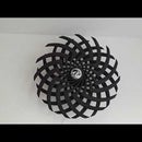
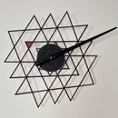
Use the template attached to cut the vinyl using a Silhouette Cameo / Studio Cutter. Alternatively you can print the PDF and cut manually.
- Stick the vinyl sheet onto the acrylic sheet carefully - avoiding any bubbles. You can use a plastic squeegee to help.
- Stick the decoration piece on the top right - I used a laser-cut piece from Michaels - but you can stick anything that catches your fancy.
- Stick a foam core board on the back side to act as a diffuser to ensure the LEDs look good.
- Stick the LED strips to the foam core using tape in the following order:
- Piece 1 - behind dates 1-15
- Piece 2 - behind dates 16-31
- Piece 3 - behind the months
- Piece 4 - behind the lower row of icons
- Piece 5 - behind the upper row of icons
- Stick the OLED in the window - ensure it is the right side up.
- Stick down the wires and boards with cello tape to ensure there are no shorts.
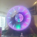
You can use the test sketch to align the LEDs (second image)
Step 6: The Sketch
Upload the following sketch to the ESP-12 using the programmer circuit described above
-- The sketch is currently in development - I had it working on a xadow module, however need to re-write it for the ESP-12 as the FastLED library currently does not support the ESP8266 chipset.

Participated in the
Time Contest


