

Introduction: Line Follow Robot, No Programming Required


This is the line following robot which i designed and built for an NCEA electronic design assessment. the idea came to me when playing around with light dependent resistors (LDR's), realising that the motor speed can be varied when wired in series with the LDR and a transistor. I decided to name the robot HEMI, simply because of its hemispherical shape.
Step 1: Overview

You will notice that the pictured robot is built to micro dimensions(it measures 45mm in diameter), but this isnt neccesary, and this instructable will explain how to build it according to the parts that you can get hold of. the line follow robot is a great first robotics project, giving you good idea of how to achieve autonomous behaviour using simple electronic components and some mild soldering skills.
parts needed include:
an NPN transistor
a resistor (the value of which later be determined later)
batteries (between 6 to 12 volts depending on size of robot and motor requirements, I used two 3v button cells).
two motor and gearbox assemblies
a switch
a light dependent resistor (LDR)
and a suitable shell. (mine was the clear case from a toy, it measures 45mm in diameter).
a multimeter or ammeter
note: the picture does not include the transistor because at the time of taking the picture i was still in the process of designing and didnt think that the transistor was neccesary. also, only one resistor was needed.
Step 2: Design


The circuit, and placement of components is the most important part of the design, I will explain the two diagrams given above.
the right motor is wired in series with an LDR and a transistor. the LDR is placed at a 45 degree angle to the driving surface and recieves light reflected from this surface. when the surface is black, less light is reflected onto the LDR, when the surface is white, more light enters the LDR.
the resistance of the LDR varies depending on the amount of light entering it. (most LDR's varie between 3000 ohms when light and 10000+ ohms when dark) this means that the current is varied coming out of the LDR. a transistor is used to "bump-up" this current to make it sufficient to drive the motor. therefore the righthand motor will be "high" (lots of current) when on a light surface, and will be "low" (no current) when on a dark surface. the left motor recieves a constant current so always remains on however it is wired in series with a resistor which makes it spin slower than the right motor when the right motor is "high". this means that the robot zig-zags along the side of a black line.
Step 3: Assembly


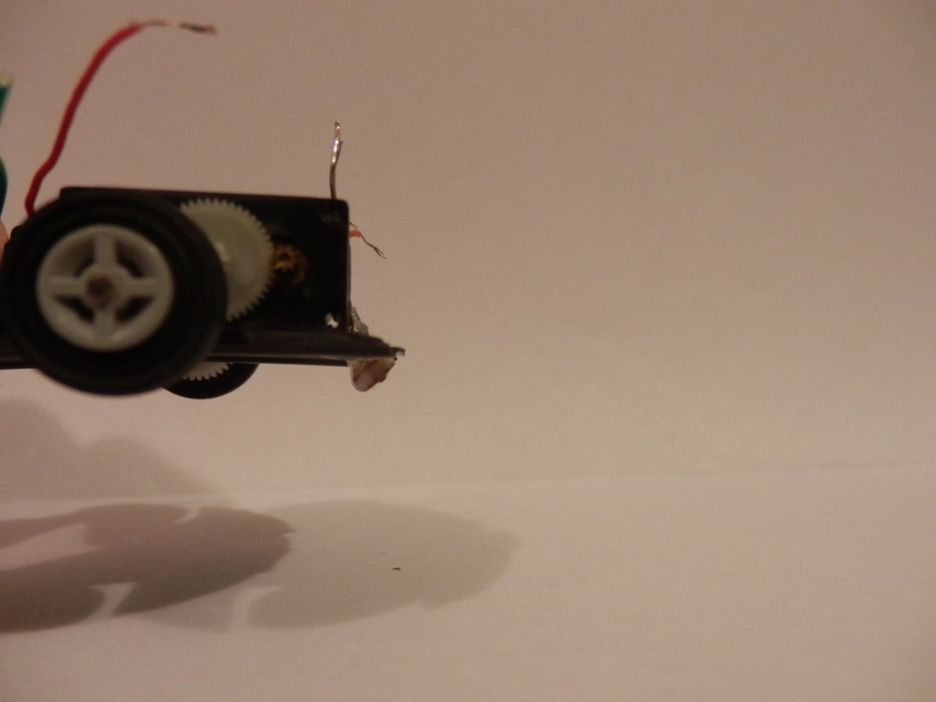
my base plate is a round pice of plastic cut out from a plastic container. i cut slots in it for the wheels, switch and LDR. the motor and gearbox/assemblies are simply attached with hot glue along with the switch. the LDR is a bit more tricky as it has to be mounted at a 45 degree angle to the ground and it most protrude from thebottom of the base by the same amount as the wheels because it also doubles as a bogey wheel to keep the robot stable. a pictue is shown of how mine was placed on the bottom of the robot.
also i chose to cut out a small piece of PCB to solder my components onto. this sat nicely on top of the motor assemblies.
Step 4: Diagnostics


the best thing to do for this step is to mount all components into a breadboard , and do a simulation by holding the LDR against a black and then a white surface at the right angle. the results can be found by measuring the current from the the emmitor leg of the transistor. the results that i found were 0 amps when the surface was black, and 0.6 amps when the surface was white.
this means that the left motor wants to recieve a constant current of about 0.3 amps. we can work out what the resistance needs to be by putting the data into the equation r=v/i (where r=resistance, v=voltage and I=amps) so: 6/0.3 = 20ohms. we need a 20 ohm resistor.
i also added a final design to give an idea of how the circuit will fit onto the PCB board.
Step 5: Soldering


all components were soldered onto the copper side of the PCB board. wires from the motors, switch and LDR were pushed up from underneath and soldered into place. the battery holders were formed from some bent paperclips.
.
Step 6: Enclosure


all that is needed to do now is finish off the robot by attaching the enclosure, then the robot is ready for a test run. set it down with the switch turned on and the LDR over the top of the black line.you will find that the robot will only work correctly under certain light conditions, so there may be a bit of trial and error to find the right lighting for it to work, but this shouldn't be too much of a problem.
unfortunately my computer would not allow me to upload a video, but i have added some extra pictures.

Finalist in the
Kit Contest

Participated in the
Battery Powered Contest


