12V NE555 PWM Controller Under $3
Intro: 12V NE555 PWM Controller Under $3
While making my mini table saw I bought a 12 V motor speed controller module from eBay. Fair enough, I thought ... that was an easier and straight forward solution. But then I decided to make my own.
I did some hunting around on the interweb and found a pretty good starting point in Circuits Today, but then, I needed to make some modification and tweaking of the circuit. I wanted to add in a toggle switch, a DC power socket and a 2 pin screw terminal into the design to make it easier to make and use.
There were some other minor alterations that I made to the design as I went, for convenience and to meet my specific needs.
I also want to point out that this circuit is not simply a motor speed controller, but a PWM controller. On the one hand, that means that it can do a lot more than just vary the speed of a DC motor. This circuit will output a 12 volt current with a varying duty cycle. It can be used as 12 V DC:
- Motor Speed Controller;
- LED Dimmer;
- Heat controller for a Polystyrene Hot Wire cutter;
- voltage controller for an electrolytic etcher; and
- etc.
The applications for this circuit are limited only by its 12 V DC nature. How you apply that is up to your imagination and experimentation. For instance, I'm thinking of using this circuit to make a vibrating platform for agitating my PCB production acid bath ...
Parts you will need
All parts were purchased from eBay.
- 1 x 0.01 uF ceramic capacitor
- 1 x 0.1 uF ceramic capacitor
- 2 x 1N4001 rectifier diodes
- 1 x 1N4004 rectifier diodes
- 1 x IRF530 100 V 14 A TO-200AB MOSFET
- 1 x TO-220 heat sink
- 1 x 2 pin screw terminal
- 1 x DC Barrel Jack (female)
- 1 x 100 ohm resistor
- 1 x 1k ohm resistor
- 1 x SPDT toggle switch
- 1 x NE555 timer IC
- 1 x 8 pin DIL socket
- 1 x 100k ohm potentiometer
- 1 x 70 x 100 single sided PCB
- some connection wire
All of this cost me around $2.90 AUD
STEP 1: The Circuit PDF
These PDF provide you with the printable circuit board for producing the NE555 PWM controller.
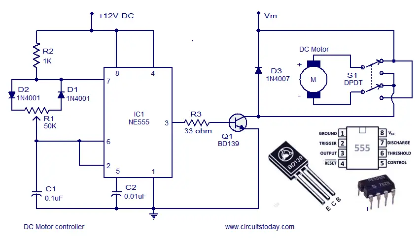
- C1 - 0.01 uF
- C2 - 0.1 uF
- D1 and D2 - 1N4001
- D3 - 1N4004
- R1 - 100 ohm
- R2 - 1K ohm
Take care with the orientation of the 555 timer and note the notch location. All other parts are pretty clearly indicated on the board.
There are 3 jumpers on the board. From GND to C1, from pin 7 of the 555 to D1 and from GND to the IRF530 Source pin.
The switch (top left) is not labelled in the PCB view, however, it is pretty straight forward. Also, there is a through hole below the IRF530, this is for the post of your heat sink.
As I want to connect the potentiometer and the switch through an enclosure, I've broken them out via wires soldered into the board. Feel free to mount this however you like ;)
When you connect your motor to the screw post, test the motor direction before committing yourself to the orientation. The motor will run in either direction, the choice is yours.
STEP 2: Motor Bracket
I looked around on the interweb for suitable motor brackets and they were all either too expensive or took too long to arrive. I've got 15 of these suckers that I want to mount in various tools and projects ... so I needed to make something extraordinarily cheap and durable.
My solution was to simply cut up some angle aluminium and drill holes in it to fit my motors.
One angle piece has a hole for the axle and a threaded hole for a grub screw to hold the motor in place. At the back, there is another angle piece with a hole drilled through it for the rear axle mount. The two angle pieces are screwed together via yet another threaded hole. I've also drilled holes through the base so that the bracket can be mounted wherever I need to mount it (depending on the project!).
The biggest hassles with this method are:
- having the right size angle aluminium stock
- cutting the angle aluminium to fit between the motor connection points
- cutting the threaded holes ... I'm using a 2mm drill bit to make M3 holes
- grinding down the M3 bolts so that they sit flush
Anyway, making the brackets doesn't take long and, because it's aluminium, it is durable, light and cheap.
Well ... on to the next project!
27 Comments
manudmaker 3 years ago
baelza.bubba 3 years ago
Patukutu 3 years ago
I need assistance. I'd like to make the same thing only now for a 12v AC motor. What should I do?
m3vuv 4 years ago
baelza.bubba 4 years ago
m3vuv 4 years ago
m3vuv 4 years ago
baelza.bubba 4 years ago
Didactech 5 years ago
rkondner in that 555s have a horrible output waveform and the bi-polars are short of the rail by over a volt. I am using this output format with uSec. pulses and someone wrongly said that the 555 cannot drive this output and I wondered why he said that.
Anyone building this circuit should consider fitting a load resistor for, say, 10mA so that the 555 output actually has some work to do rather than simply waving at the FET gate.
BeachsideHank 7 years ago
What, in your opinion as the designer, is the maximum safe current one would expect this unit to pass?
Nice build too, I like it!
baelza.bubba 7 years ago
oh ... and thanks ;) I'm glad you like it.
MattyJ3 5 years ago
Sorry I think my question was misleading. I meant to ask is it possible to get an output voltage 0V to +15V (rather than +5V to +15V)?
Thanks again
baelza.bubba 5 years ago
Okay, I understand your question now :) The limiting factors to get to 0V, then, are the minimum supply voltages for the various components. The NE555 datasheet says that the operating range for the chip is 4.5 - 18 volts, so the unit will not operate on less.
But from a functional perspective, the PWM duty cycle can be 0% so that would result in no supply to the IRF530.
Obviously, the circuit will not operate at 0V, but nor would it work at less than 4.5V. On that basis, you would be limited to 4.5 volts on the input side.
On the output side, you could implement a variable voltage regulator or a DC-DC buck converter to step down voltage (and step up current), there are plenty of 'structables for buck converters ;)
Good Luck, MattyJ3
baelza.bubba 7 years ago
Hey BeachsideHank, the operating limitation in this circuit is the 555 timer. This piece has an operating limit of +5 to +15 volts. You could get around that by using a regulator on the input side (say LM7805) and using a transistor to switch the other side of the circuit for higher voltage. You would also have to have a different supply connection as the DC barrel jack is only rated to 18 volts. The 1N4001 is rated to block 50 volts and 35 volts reverse voltage ... so you could conceivably replace the rectifying diode with a 1N4004 to increase it to 400/280 volts respectively. This would then mean that the IRF530 would be your limiting factor 100 V 14 Amp.
Having said that ... 15 volts is the limit of this design ;)
MattyJ3 5 years ago
How come this piece has an operating limit 0V? Is there anyway to alter it to 0V to +15V?
Like the design and instructions, really helpful.
baelza.bubba 5 years ago
Hi MattyJ3, the NE555 has an upper limit of 15V, so that's the main limiting factor in the design, if the input is less than 5V, the NE555 doesn't do it's thing (create a square wave, in this application). There are a couple of things mentioned above that would increase the upper limit of the operating voltage, but, there are a bunch of low voltage rated parts to consider (DC Barrel Jack and NE555 mainly).
Does that help?
rkondner 7 years ago
Hi,
I have used 555 devices for a long time and the part you are calling out is, I believe, a bipolar parts They also make CMOS version of the part and I find them very superior.
The 555 outputs will drive a FET fine at low frequencies which is probably ok in this application. For higher powers / voltages you might try a CMOS device or get a FET driver. What I have seen in 555 outputs is a small glitch in the output where both the pull up and pull down transistors are both off. Bipolar transistors exhibit storage times and IC designers make darn sure there is a dead time when both transistors are off. Both being in a conducting state at the same time is very bad. CMOS transistors do not have a storage time. This output glitch could result in large switching loss.
Also, reconsider the 100 ohm gate resistor. Typically 5 ohms is plenty and I worry that 100 ohm would introduce high switching loss. I noticed a small heatsink on your FET. Going to a CMOS parts and dropping the gate resistor could make a big difference. I would love to hear if that helps.
And be sure to hang a scope on the drain, I always check for stray inductance requiring a snubber. Take a look at the FET switch in the SunDuino schematic I used in some power supply designs, you will see examples of what I am suggesting. (www.sunduino.com)
Be sure to post what you try, I am curious if you can drop loss to where that heatsink is not required!
Thanks, Bob K.
baelza.bubba 7 years ago
For the application tgat I have and considering the cost, this design is still a satisfactory solution. The drain resistor will drop, though!
jwzumwalt 7 years ago
The critical info for any power supply is input/output voltage, and max current. I suggest you provide that information within the first one or two paragraphs to allow readers to quickly identify whether the project is suitable for their purpose.
Input/output: +5 to +15 volts
Current: 14 amps
I almost passed this up once I saw the 555, thinking it would be limited by its 200ma. Using the 14 amp switching MOSFET makes this a truly useful pwr supply, but that info needs to be "up front". The min/max pulse width should also be provided. This is a nice project and I'll build one :)
baelza.bubba 7 years ago