

Introduction: Arduino-Based Optical Tachometer


Over ten years ago, I put up a web page with detailed instructions on building a simple electric motor based on one from the Beakman's World TV show. I called it the "Beakman's Electric Motor" page and over the years it has had hundreds of thousands, if not millions, of hits. Realizing that just building a motor, no matter how cool, wasn't a good science fair project, I added suggestions for using the motor as a science fair project, such as experimenting with different magnets, batteries, and coil constructions and seeing how they affect performance. In order to do this, the speed of the motor should be measured, but I left that as an open-ended question.
I've had dozens of e-mails over the years asking how to measure the speed and I've always suggested using a broken light beam and a counter, but I've never built one myself. I even suggested to one person that they use a slot-car lap counter since I'd seen on one sale at Toys 'R Us for 99 cents and she said that it worked perfectly, but not everyone can find a good deal like that.
It just so happened that I got one of these "how do I measure the motor speed?" e-mails on the same day my new Arduino Diecimila microcontroller board arrived from the Make Store, so I thought that would make a great weekend project.
Here is the result, an optical tachometer for Beakman's Electric Motor using an IR emitter/detector pair and a Arduino board. With a few modifications to the programming, you can use this tachometer for measuring other things such as fan or propeller speed. Notes are included on what to change for different applications.
How to have fun with Arduino is a good source of basics on how to setup and use the Arduino board.
Step 1: Materials Needed


Arduino Diecimila Board
Available from the Make Store or from several other online resources. Note however that the techniques of this Instructable could be adapted for other microcontrollers and circuits.
Computer with Arduino software and USB cable
IR LED and IR phototransistor
I used a Radio Shack #276-142, but that may be an old part number. Parts selection on this probably isn't too critical.
Visible light LED
I used a high-brightness red one that I had around. Actual selection not too critical.
10K Ohm resistor
220 Ohm resistor
Breadboard (semi-optional), hookup wires, clips
Opaque tape, such as black electrical tape
Framework for holding LED and detector
Use your imagination, I used KNex pieces to build a frame.
Beakman's Electric Motor (or something else to measure)
Original instructions for building the motor are here: Beakman's Motor
Similar plans are available from other places, such as this Instructable:
Simple Electric Motor
Step 2: Building and Preparing the Motor (if Necessary)

Follow the instructions to build the Beakman's Electric motor. The motor should be mounted on a suitable base so that it can run freestanding a bit off the table. I used some Brio construction set pieces (I have a lot of toys laying around).
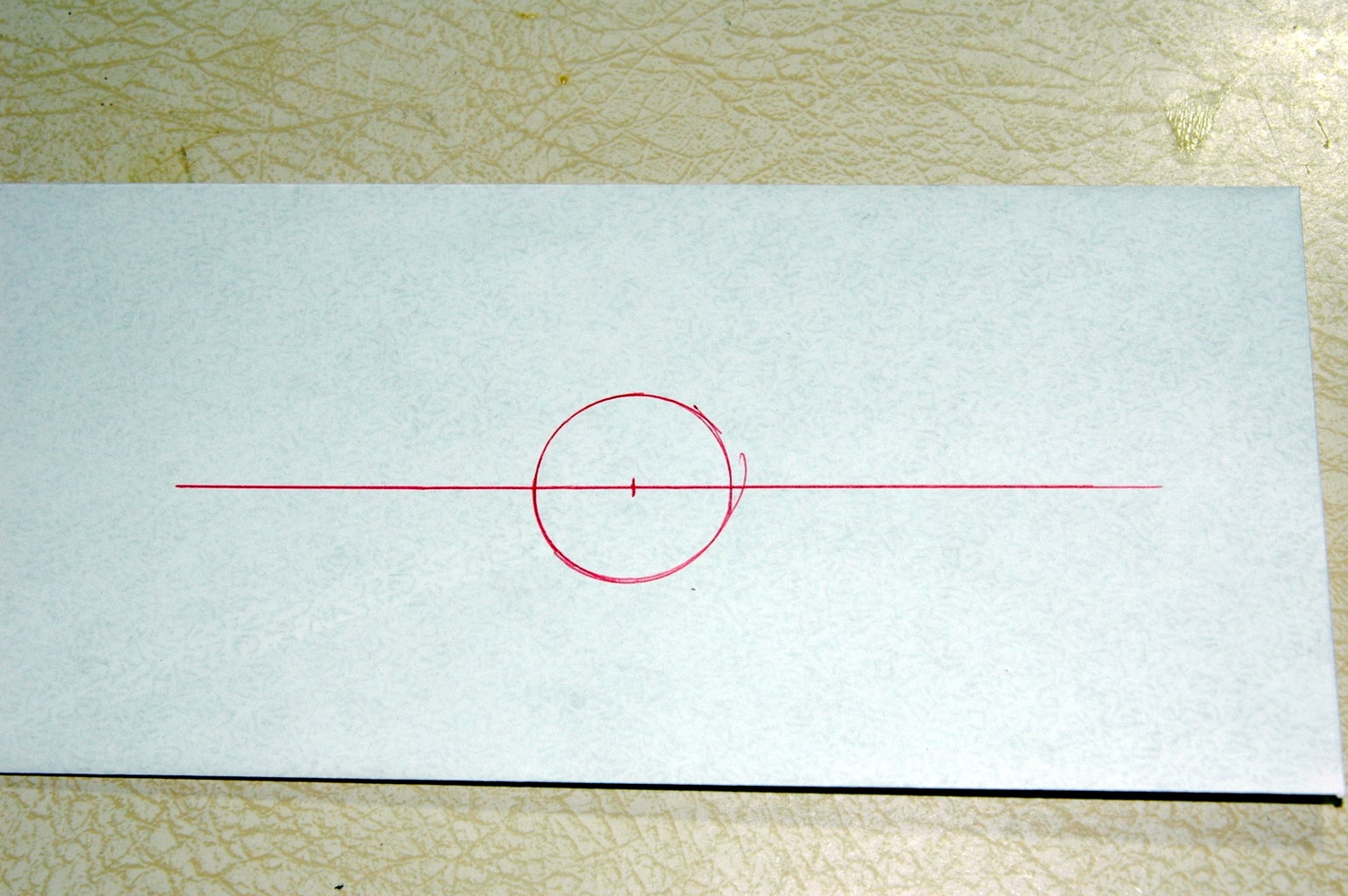
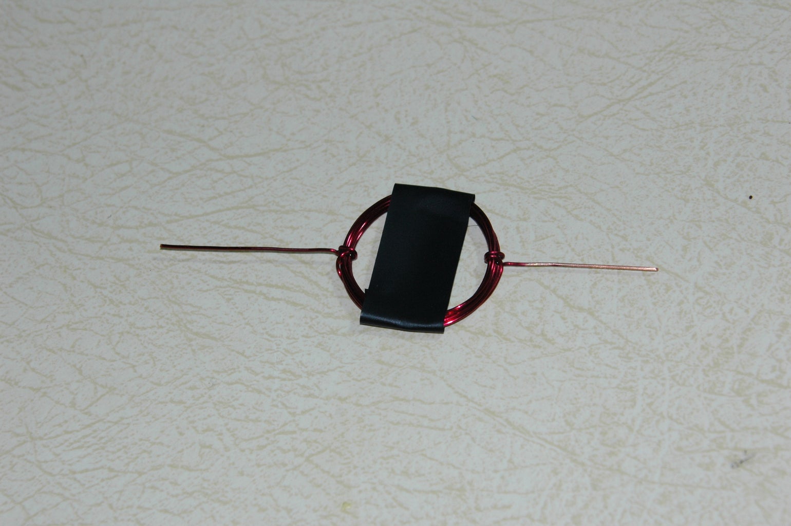
The most important thing to ensure reliable motor operation is to make sure the coil is balanced and the tails of the coil are very straight. I drew a diagram using my coil form and a ruler, then laid the completed coil on the paper to align the tails perpendicular to the coil and to make sure they were straight. I then used a drop of superglue where the tails were wrapped around the coil to make sure they couldn't slide.
To enable the coil to break the light-beam, place a piece of opaque tape (I used black electrical tape) across the coil. This might slow it down a tiny bit, but if all of your coils have the same sized piece of tape in the same position, your results between coils should be relatively consistent.
Step 3: IR Detector Circuit


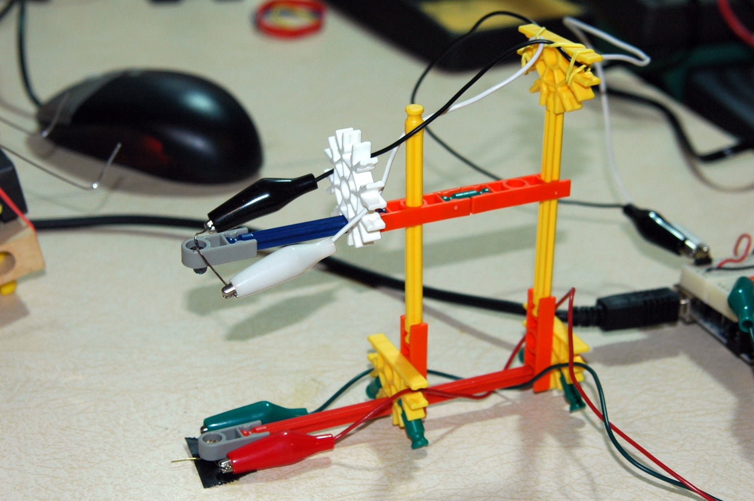
There are three separate circuits to connect to the Arduino. You can refer to my schematic and notes sketch in the images and to the pictures of the breadboard to see how I hooked it all up. Of course, the critical things to note are the anode/cathode orientation of the LEDs and transistors and the connections to power and ground. The whole circuit is powered from the Arduino board and since the program will communicate with the PC, I'm using the USB connector for power.
IR Detector Circuit
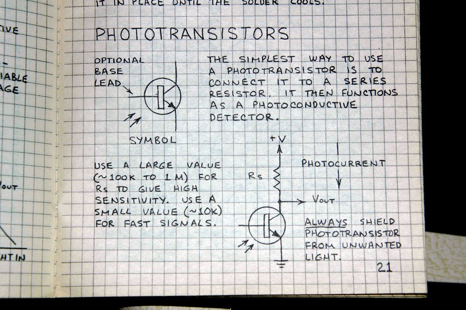
I figured the easiest way to detect breaks in the light path was to use an IR LED and IR phototransistor, configured so that the phototransistor is either "on" or "off" instead of using a photocell with an analog threshold.
I found the configuration in the Forrest Mims circuit notebook "Optoelectronic Circuits" - the excerpt is in the images below. These books are wonderful, by the way. I'm anxious to try many of the other sensors and circuits he describes in them with the Arduino.
A 10K Ohm resistor goes from the +5V connector on the Arduino to the collector on the phototransistor (pin 2). The emitter of the phototransistor (pin 1) is connected to ground (again on the Arduino board). Pin 3 is unused and can be bent out of the way or clipped. The collector (pin 2) is also connected to the digital pin 2 on the Arduino. Input 2 on the Arduino corresponds to interrupt 0, which we will be using to count pulses.
I used alligator clip patch wires to connect the phototransistor and small angled pins on the breadboard to connect to the circuit. The hookups for this project are simple enough that you could probably do point-to-board wiring and just plug the hookup wires into the sockets on the Arduino. I used a small breadboard instead. Of course, if you have the Arduino shield, construction would be even easier.
IR LED Circuit
The Arduino Diecimila has a current limiting resistor on pin 13, so to reduce the parts count, I connected the IR LED to that pin. If you have an older Arduino board, remember to connect an appropriate series resistor to the output pin. The connections for this were also done with a right-angled header on the breadboard and alligator clip patch wires to the LED. Anode to digital pin 13, cathode (flat side) to ground.
Status LED
Since we're dealing with invisible IR light, interrupts, and serial communications for status, I wanted to see something that would tell me the circuit is working, so I connected a RED status LED to digital pin 12 through a 220 Ohm series resistor.
IR Detector Circuit
I figured the easiest way to detect breaks in the light path was to use an IR LED and IR phototransistor, configured so that the phototransistor is either "on" or "off" instead of using a photocell with an analog threshold.
I found the configuration in the Forrest Mims circuit notebook "Optoelectronic Circuits" - the excerpt is in the images below. These books are wonderful, by the way. I'm anxious to try many of the other sensors and circuits he describes in them with the Arduino.
A 10K Ohm resistor goes from the +5V connector on the Arduino to the collector on the phototransistor (pin 2). The emitter of the phototransistor (pin 1) is connected to ground (again on the Arduino board). Pin 3 is unused and can be bent out of the way or clipped. The collector (pin 2) is also connected to the digital pin 2 on the Arduino. Input 2 on the Arduino corresponds to interrupt 0, which we will be using to count pulses.
I used alligator clip patch wires to connect the phototransistor and small angled pins on the breadboard to connect to the circuit. The hookups for this project are simple enough that you could probably do point-to-board wiring and just plug the hookup wires into the sockets on the Arduino. I used a small breadboard instead. Of course, if you have the Arduino shield, construction would be even easier.
IR LED Circuit
The Arduino Diecimila has a current limiting resistor on pin 13, so to reduce the parts count, I connected the IR LED to that pin. If you have an older Arduino board, remember to connect an appropriate series resistor to the output pin. The connections for this were also done with a right-angled header on the breadboard and alligator clip patch wires to the LED. Anode to digital pin 13, cathode (flat side) to ground.
Status LED
Since we're dealing with invisible IR light, interrupts, and serial communications for status, I wanted to see something that would tell me the circuit is working, so I connected a RED status LED to digital pin 12 through a 220 Ohm series resistor.
Step 4: Programming

The program for calculating the RPM of the motor is pretty simple. I adapted it from a Hall Effect motor speed calculator at the excellent Arduino Playground site.
You can download the "sketch" for the program below.
The rpm_fun function is the interrupt function that will be called whenever the data on pin 2 changes from HIGH to LOW (a FALLING pulse). It updates the global rpmcount, then toggles the status LED.
Setup initializes the variables, configures the serial parameters, sets the pin modes, and sets up the interrupt function.
The loop function, as the name implies, is the main processing loop that "runs forever" while the board is powered up. The first statement delays for one second (1000 milliseconds), but note that the interrupt function will break in every time the value of pin 2 changes and run the rpm_fun function. After the 1 second delay, the interrupt is temporarily disabled (this may not be necessary, but seems safer) then the RPM is calculated based on the number of interrupts and the elapsed time between now and the last time the calculation occurred. The result is sent back to the computer over the serial port, then the interrupt is restored.
Note that the way the motor and the IR detector is configured, each single turn of the coil will result in two transitions, so the calculation takes that into effect. The same would occur for a two bladed fan or propeller. If only one light break per revolution occurred, such as a swinging arm, the calculation would be:
For a three bladed fan, the calculation would be:
You can download the "sketch" for the program below.
The rpm_fun function is the interrupt function that will be called whenever the data on pin 2 changes from HIGH to LOW (a FALLING pulse). It updates the global rpmcount, then toggles the status LED.
void rpm_fun() { //Each rotation, this interrupt //function is run twice, so take //that into consideration for //calculating RPM //Update count rpmcount++; //Toggle status LED if (status == LOW) { status = HIGH; } else { status = LOW; } digitalWrite(statusPin, status);}Setup initializes the variables, configures the serial parameters, sets the pin modes, and sets up the interrupt function.
void setup() { Serial.begin(9600); //Interrupt 0 is digital pin 2, so that is where //the IR detector is connected //Triggers on FALLING (change from HIGH to LOW) attachInterrupt(0, rpm_fun, FALLING); //Turn on IR LED pinMode(ledPin, OUTPUT); digitalWrite(ledPin, HIGH); //Use statusPin to flash along with interrupts pinMode(statusPin, OUTPUT); rpmcount = 0; rpm = 0; timeold = 0; status = LOW; }The loop function, as the name implies, is the main processing loop that "runs forever" while the board is powered up. The first statement delays for one second (1000 milliseconds), but note that the interrupt function will break in every time the value of pin 2 changes and run the rpm_fun function. After the 1 second delay, the interrupt is temporarily disabled (this may not be necessary, but seems safer) then the RPM is calculated based on the number of interrupts and the elapsed time between now and the last time the calculation occurred. The result is sent back to the computer over the serial port, then the interrupt is restored.
void loop() { //Update RPM every second delay(1000); //Don't process interrupts during calculations detachInterrupt(0); rpm = 30*1000/(millis() - timeold)*rpmcount; timeold = millis(); rpmcount = 0; //Write it out to serial port Serial.println(rpm,DEC); //Restart the interrupt processing attachInterrupt(0, rpm_fun, FALLING); }Note that the way the motor and the IR detector is configured, each single turn of the coil will result in two transitions, so the calculation takes that into effect. The same would occur for a two bladed fan or propeller. If only one light break per revolution occurred, such as a swinging arm, the calculation would be:
rpm = 60*1000/(millis() - timeold)*rpmcount;
For a three bladed fan, the calculation would be:
rpm = 20*1000/(millis() - timeold)*rpmcount;
Attachments

Step 5: Putting It All Together
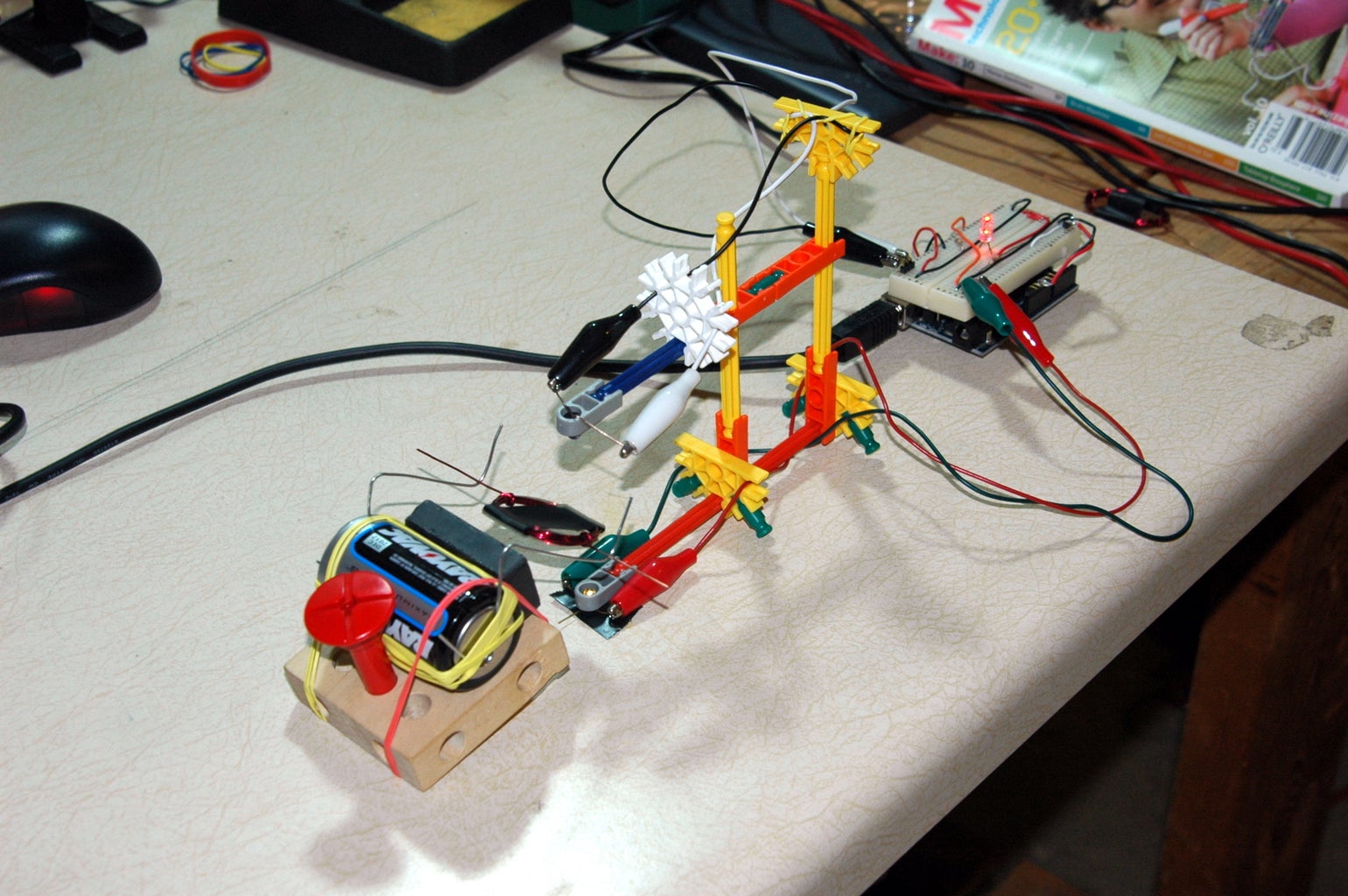

The IR LED should be pointed at the IR detector over a gap of a few inches. While you can tape the detector to the table and hold the IR LED in your hand (as I did during testing), this is pretty awkward. What you want to do is to build a makeshift frame that keeps the emitter and detector aligned, but leaves enough space that the motor coil can rotate between them and break the light path with the strip of tape.
I built a KNex frame where the upper arm can slide up and down and used rubber bands to secure the wires that go to the LED and phototransistor, but you can whatever you can find - LEGO, Popsicle sticks, stiff wire, whatever.
You can test to see if the circuit and program is working by downloading the sketch to the Arudino and using your finger to break the light beam between the LED and photodetector. Every time you break the beam, the status LED should toggle on and off. You can turn on the serial monitor in the Arduino software and you should see a "0" being out every second. If you break the beam a few times, the "0" should change to a small number.
If that is working, you are ready to integrate the motor.
Get the motor spinning with the tape on the coil, make sure the detector circuit is working and the serial monitor is on, then slide the motor in between the LED and detector. If everything is working, the RPM of the motor should show up on the serial monitor on the PC.
The best performance I've got so far was around 1200 RPM. Leave comments if you do better and what you did differently!
Step 6: Future Steps
The whole point of this was to enable people to measure the motor speed of the Beakman's Motor so they could vary details and measure the effect the changes have on the motor speed and I think this succeeds in providing those measurements.
However two improvements come to mind already. The first would be to easily capture the RPM information so that it could be graphed and averaged. Since it is just numbers coming across a serial port, this shouldn't be hard to do in any language.
The second is to use the Processing language to create a graphical tachometer display, either a big analog dial or a digital display with a graph, to show the data instead of just reading numbers off the serial terminal.
Processing Home Page
Any other ideas?
Here are a few more resources on the motor, including some EE lab handouts where the motor is one of their projects:
Fields and Waves Handout
Comments on Motor Design
A few more pictures are available on my Flickr page.
Another introduction to this project (and other random stuff) can be found on my blog, Avoidance Central.
