

Introduction: Using FM RC Controllers With Arduino


I recently dug up my old RC transmitter and receiver and thought "How can i control my arduino with this?" so i powered on my scope to see what was going on at the receiver. Sure enough, it was sending out the standard PWM signal that servos use. Now I just needed something to control. What's easy and fun to control? LED's of course.
Step 1: The Receiver
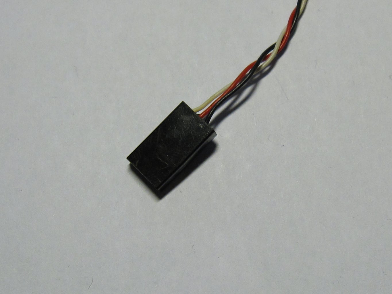

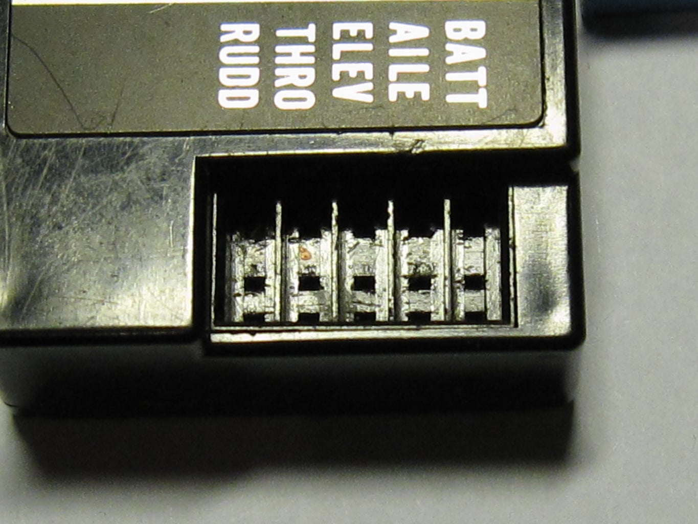
To begin with i had to figure out what pin on the receiver was the signal pin for the servo. I found an extension cable, there i could clearly see what pin it was.
Step 2: Connecting It All


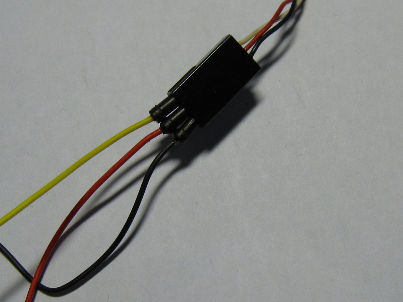
Now that i knew what pins were what i connected them to the arduino as follows:
I connected the signal to pin 8
and the led was connected to pin 11 because it has PWM capabilities.
I also connected the receiver ground to the arduinos ground and the 5v out from the receiver to the Vin on the arduino
I connected the signal to pin 8
and the led was connected to pin 11 because it has PWM capabilities.
I also connected the receiver ground to the arduinos ground and the 5v out from the receiver to the Vin on the arduino
Step 3: The Code


Now i started coding,
I used the pulseIn() function to read the pulses from the receiver and send them to the serial monitor, when i had those values i told the arduino to map those to the PWM values (0-255) and send them to the serial monitor again.
Now when i moved the joystick on the remote i saw the values change.
Now the last part of the code sends those PWM values to the led and fades it accordingly.
I was happy when i got this working but i needed a bit more challenge, i wanted it to control an RGB LED.
Step 4: Connecting the RGB LED

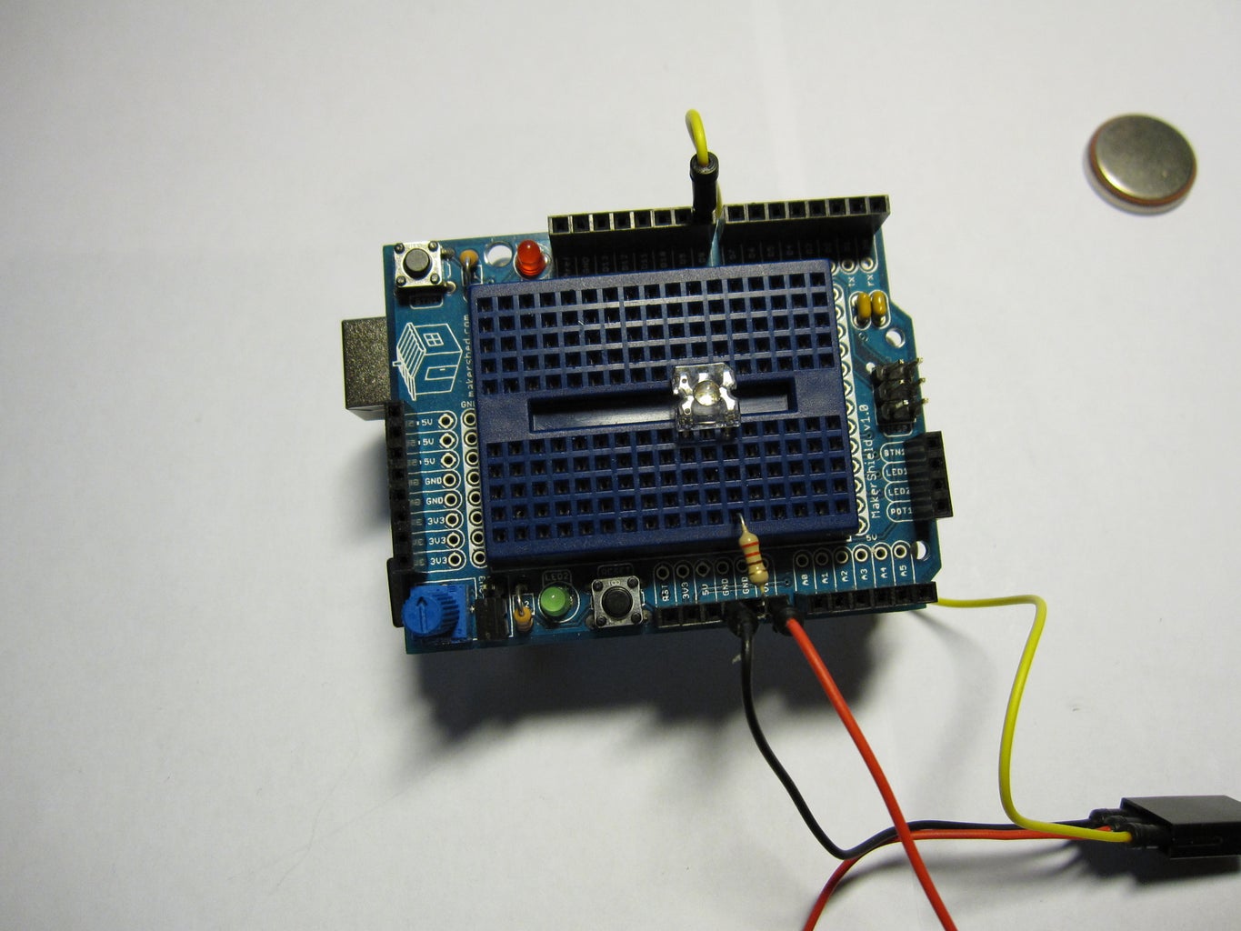

Now, since i wanted RGB i would need to read three lines from the receiver, that was no problem since i already knew what lines to connect to the arduino.
I kept one output on pin 8
the next output was connected to pin 7
and the last to pin 6
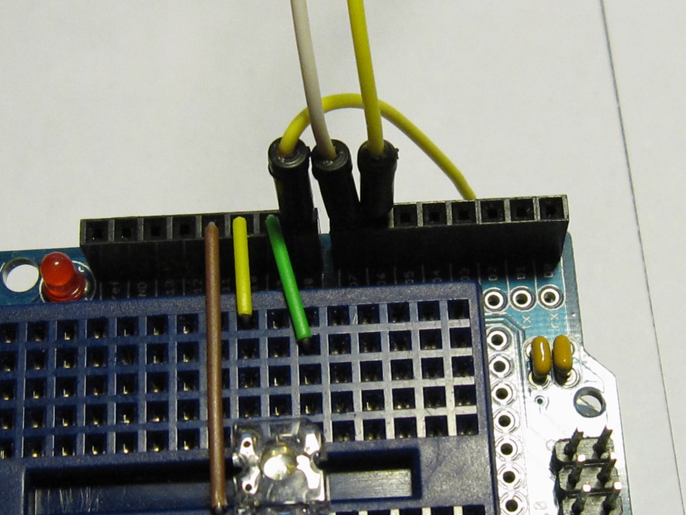
Since i was going to use an RGB led i decided to use my protoboard.
The ground of the led was connected to Gnd of the arduino using a 220 ohm resistor
the red was connected to pin 11
the green was connected to pin 10
and the blue was connected to pin 9
I kept one output on pin 8
the next output was connected to pin 7
and the last to pin 6
Since i was going to use an RGB led i decided to use my protoboard.
The ground of the led was connected to Gnd of the arduino using a 220 ohm resistor
the red was connected to pin 11
the green was connected to pin 10
and the blue was connected to pin 9
Step 5: RGB Code

Now I just altered the code a bit to add two more led's and two more inputs.
I also removed the serial commands because i didn't need to debug it anymore.
Then i uploaded it and it worked fine :)
I also removed the serial commands because i didn't need to debug it anymore.
Then i uploaded it and it worked fine :)
Step 6: Conclusion
Just imagine the possibilities with this, these don't have to be led's.
It can also control the speed of any motor, just as long as you have different values for different positions of the joysticks you can do virtually anything with this.
The codes are here :)
It can also control the speed of any motor, just as long as you have different values for different positions of the joysticks you can do virtually anything with this.
The codes are here :)

