

Introduction: 2D Contour Toolpaths


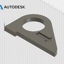
Finally, you want to machine the outer profile of the pushstick using a Contour Toolpath. In this type of toolpath, the tool will follow a contour, or a line. Contours can be open or closed and can be on different Z-levels, but they must be flat (2D). While a pocket toolpath fills in an area, a contour just follows a line.
1) Turn on the visibility of the model.
2) In the ribbon, choose 2D>2D Contour.
3) Click Select next to Tool, and choose a 3/8" flat endmill. Click OK.
4) Change Spindle Speed to 12,000 rpm, and Cutting Feedrate to 75 in/min.
Step 1:


Step 2:
5) Click the Geometry tab.
6) Click the outer and inner contours of the part.
7) Zoom in on the inner circle. The red arrow represents the direction and side of the contour that will be machined. Right now, you can see that the tool will move clockwise on the outside of the contour. You want the tool on the inside of this contour.
8) To switch the direction and side of the contour the tool will machine, click the red arrow once.
Step 3:

Step 4:
9) From a top view of the part, check Tabs.
You want to add tabs to this toolpath to prevent stock from coming loose while being machined. In CNC machining, it's important that your stock and workholding system are always rigid and secure. Loose parts could damage tools or the machine spindle. You will remove the tabs later with wood shop tools such as a bandsaw, chisels, or jigsaw.
10) Change Tab Height to 0.15.
11) Change Tab Distance to 6. You only need enough tabs to keep the part in place.
Step 5:

Step 6:
12) Click the Heights tab.
13) Under Bottom Height, add an Offset of -0.05.
You want this toolpath to go slightly below the bottom of the part, and into the machine bed, in order to prevent a thin "skin" of stock material from remaining on the edge of the part. Add this additional offset anytime you machine around the boundary of a part.
14) Click the Passes tab.
15) Check Multiple Depths.
16) Change the Maximum Roughing Stepdown to the correct amount, from what you know of the Stepdown and Stepover rule.
17) Click OK to generate toolpath.
18) Verify, from the side view, that this toolpath does indeed go slightly below the bottom of the part.
Step 7:


Step 8: Simulate!
1) Click Setup 1.
2) In the ribbon, click Simulate.
3) Turn off the visibility of the model.
4) Click >| to skip to the final CNC machined part.
5) Inspect the model.
This is what the part will look like after all machining operations. Zoom into the various parts and make sure they look the way you expect.
Step 9:


