

Introduction: 2D Pocket


Before you continue with more 3D operations, you're going to machine the hole in the spoon's handle. A 2D operation is appropriate here because the hole is (approximately) perpendicular to the XY plane.
1) In the CAM workspace, choose 2D>2D Pocket from the Ribbon.

2) Click Select next to Tool, and choose 1/4" Flat (1/4" EM Long) from the DMS Tool Library. Click OK.

3) Click on the Geometry tab.
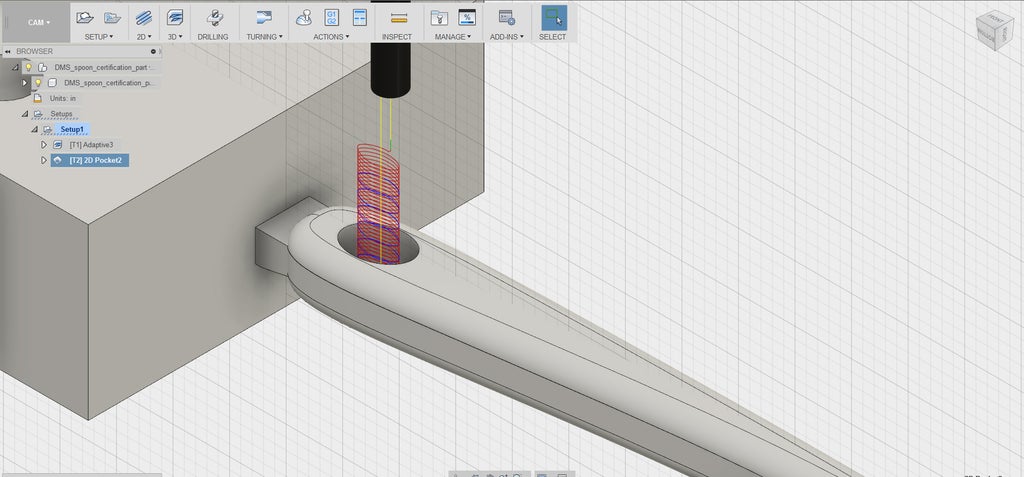
4) Zoom in and orbit so you can clearly see the hole in the spoon's handle. Carefully select the bottom edge of this hole.
View the spoon from the side. Note that the blue selection is flat along the XY plane because you are using a 2D toolpath. Your geometry is so close to flat that this doesn't make your toolpath inefficient.

5) Click on the Passes tab. Check the box next to Multiple Depths. This is how you'll ensure that the tool is stepping down, rather than running the entire toolpath at the bottom depth, which is too aggressive.
6) Change Maximum Roughing Stepdown to the maximum stepdown allowed.
You know what this is. Check your answer against the above screenshot.
7) Uncheck Stock to Leave.
You are treating this Pocket toolpath as a finishing toolpath, so you don't want to leave any stock behind.
8) Click OK to generate the toolpath.
Step 1: Edit 2D Pocket
Now that you've generated the toolpath, you'll notice that it is inefficient. It machines the air for a while before entering material.
1) Right click 2D Pocket 1, and choose Edit.

2) Click on the Heights tab.
3) Change the Top Height to Selected Contours. You'll notice there's no prompt for you to select a contour. Selected Contours refers to the contour(s) you selected in the Geometry tab, which you know is the bottom contour of the hole.
4) Change the Top Height Offset to 0.5.
This offsets the top height to 0.5" above the selected contour. When you view the spoon from the side, you'll notice that the top and bottom height rectangles (dark and light blue, respectively) do not appear. This is a software glitch that occurs when you use Selected Contour. In real life, when you're not following a lesson, you may have to do several trial-and-error attempts to get the correct height offset.

5) Click OK to generate the toolpath. You can immediately see that it's much more efficient now.
6) To show you a way to address the issue in Step 4 of not being able to view top and bottom heights, here is another way to set heights. Right click Pocket 1 and choose Edit. In the Heights tab, for Top Height, choose Stock top with an Offset of -0.6. The light blue rectangle corresponding to the top height appears on the screen. You can see that it lies above the top of the hole in the handle. Now change Bottom height to Model bottom. Play around with the offset number until the dark blue Bottom Height rectangle gets close to the bottom of the hole. For instance, try 0.35. Now click OK to generate the toolpath.
You'll see that the toolpath is basically the same as it was in Step 5. This shows you that there is often more than one way to tackle the same problem in CAM.
Step 2: Simulate

1) Click Setup 1.
Get in the habit of selecting Setup before clicking Simulate to simulate all the toolpaths you've created. Even if you're not reviewing earlier toolpaths, you need to see how the latest one you created interacts with the surfaces you've already machined. If you don't click Setup, the CAM software will only simulate the toolpath you just created. Viewing it in isolation is not useful.
2) In the ribbon, choose Simulate.
3) Ensuring that the Toolpath Mode is still Tail, and Stock is still checked, watch the simulation carefully. Note that both toolpaths appear in the timeline below the control buttons.
4) Notice that it's hard to see the end of the Pocket toolpath. In the dropdown next to Tool, choose Flute.
This turns off the visibility of the shaft and holder so you can see the bottom of this toolpath. Making the stock transparent and viewing the simulation from the side view may also be useful.


