

Introduction: 3D Adaptive Roughing


The next step after Setup is Toolpath.
For 3D parts, always start with roughing toolpaths to remove as much material as efficiently as possible. Then, use finishing toolpaths to remove the rest of the material and meet your design and aesthetic specifications. The best roughing toolpath to use is Adaptive, which is an intelligent toolpath that ensures the forces (load) on the tool remain constant. This allows you to remove material quickly without breaking the end mill.
Step 1: Create a Bounding Box
By default, 3D Adaptive machining will remove all of the stock that surrounds your model. You won't always want the toolpath to do this. For instance, if you're using clamps to hold your part down, you may need to ensure that the tool won't remove the stock near your fixtures. In this case, you want to make sure that the toolpath will only remove material directly around the model of the spoon. To do this, you will draw a bounding box to constrain the geometry of the toolpath. This is a handy trick in 3D machining, and one that comes up frequently.
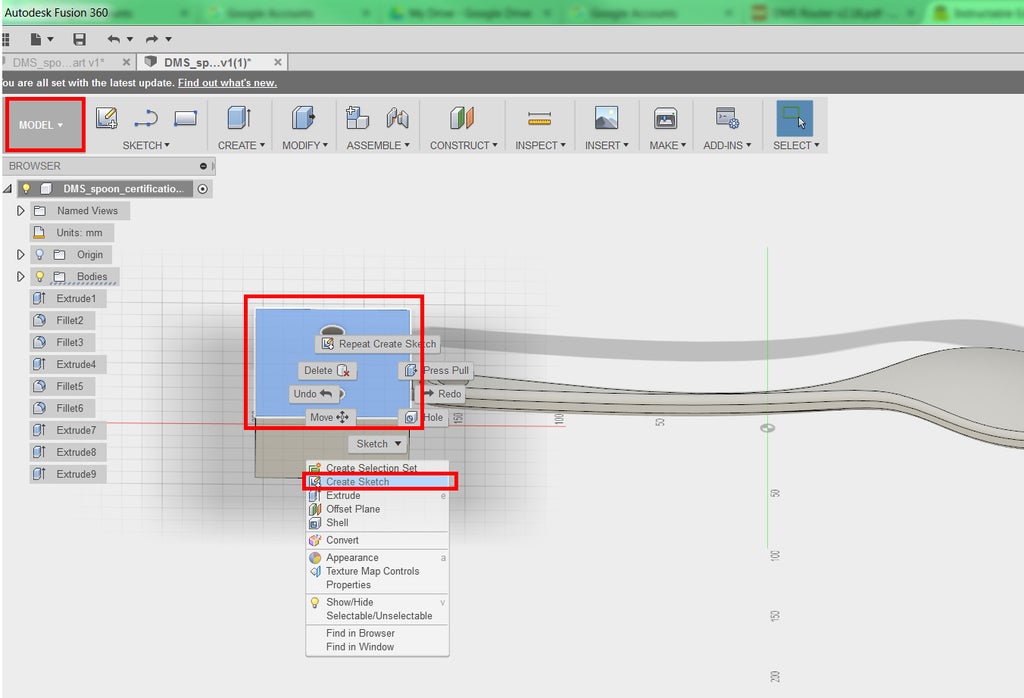
1) In the ribbon at the left, change the Workspace to Model.
2) Orbit around to the back of the spoon. Hover your mouse over the plane with the two holes in it, and choose Create Sketch.

3) In the ribbon, choose Sketch>Rectangle>2-Point Rectangle.

4) Carefully draw a rectangle that surrounds the spoon, as seen in the image.
5) In the ribbon, chose Stop Sketch.

6) Go back to your isometric view by clicking the Home icon by the view cube. In the browser tree, expand the Sketches folder. Rename Sketch 1 to "Bounding Box for CAM."
Step 2: 3D Adaptive Clearing Toolpath
Now, create the 3D Adaptive toolpath.
1) In the ribbon at the top, change the Workspace back to CAM.

2) In the ribbon, choose 3D>Adaptive Clearing.
3) Notice that the toolpath dialog features tabs, just like the setup dialog did. It's a good practice to navigate the tabs from left to right, like reading a book. You'll begin by clicking Select next to Tool.
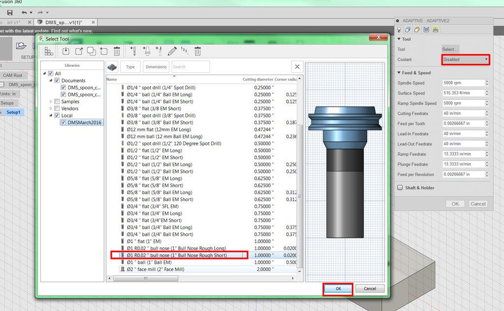
4) Choose 01 R0.02" bull nose (1" Bull Nose Rough Short) from the DMS Tool Library. Click OK.
In this case, you're roughing and want to cover a lot of area, so you'll want to choose the biggest diameter tool in the DMS tool library: 1".
3) Leave Coolant set to Disabled.
The DMS does not have coolant, and by default, the tools in the DMS tool library have coolant set to Disabled. However, if you set coolant to Flood, the dust collection shroud--two spindle-mounted pneumatic intakes connected to the wood shop dust collection system--will automatically engage during this toolpath, closing in around the tool. Dust collection is typically only engaged for certain materials, like MDF, when it's best to minimize the particulate in the air. By default, the shroud is not attached. Ask shop staff for help if you need to use it.
5) In the toolpath dialogue, click the Geometry tab.
Refrain from pressing "OK" between tabs, because that will generate the toolpath. If you accidentally do, find the toolpath on the left under Setup 1 in the browser tree, right click, and choose Edit.

6) Next to Machining Boundary, choose Selection.
Notice that the button next to Machining Boundary Selection is now teal blue and says Nothing. This means that you are being prompted to choose the boundary.
7) Carefully click on the sketch you just drew. It should turn green.

8) Ensure that Tool Containment is Tool outside boundary.
Hover your mouse over "Tool outside boundary" to see diagrams of the three options in this category: Tool inside boundary, Tool center on boundary, and Tool outside boundary. In this case, you are allowing the tool to go outside the boundary so that it can enter laterally from the sides of the stock; otherwise it would have to ramp into the stock from the top in a helix shape, which is less efficient. You can add an additional offset to this boundary, but you don't need one here.
9) In the browser, uncheck Rest Machining.
Rest stands for Remaining Stock machining. This kind of machining will only remove stock that has been left behind by the previous toolpath to make your operation more efficient. However, this is your first toolpath, so Rest Machining is unnecessary.
Step 3: Adaptive Clearing Heights and Passes
You have a few more tabs to get through before generating this toolpath.

1) Click on the Heights tab. In this tab, you control the upper and lower limits of your toolpath.
2) For the Bottom Height offset, type -0.05.
By default, this toolpath has the Stock top set as the top height, and the Model bottom set as the bottom height. Because you will have a spoiler board (scrap material underneath your stock inside the DMS), you can go beyond the model bottom to ensure that you don't leave a thin skin of stock material behind.
The value you just entered, 0.05", sets the bottom of the toolpath to be 0.05" below the bottom of the model. The endmill will lightly graze your spoiler board. Check this by viewing the spoon from the side, by clicking on a side on the view cube. You can see the dark blue line, corresponding to the bottom of the toolpath, slightly below the model.

3) Click on the Passes tab. In this tab, you control the behavior of the tool.
4) Change Optimal Load to 0.3.
Hover your mouse over the field next to Optimal Load to see the definition of Optimal load with diagrams. You can think of "amount of engagement" as another way to say stepover. That is, an optimal load of 0.3" = a stepover of 0.3". The CAM software will try to keep this level of engagement as continuous as possible to maintain a constant load, though it may need to go below this number in certain parts of the geometry, such as corners.
If you went through the Beginner and Advanced CAM Instructable, you downloaded a formula for Optimal Load. This formula is for machining in aluminum only. When using the DMS to machine wood and plastic, you'll need to manually set your optimal load.
For machining wood or plastic, follow the Stepover and Stepdown Rule: The stepover and stepdown should never exceed 50% of the tool diameter.
In this case, the tool has a diameter of 1". To be conservative, you set the stepover to 30% of tool diameter, or 0.3".
5) Change the Maximum Roughing Stepdown to 0.5.
A stepdown is the depth of each pass in the Z-direction. You have set the maximum stepdown to 50% of the tool diameter, following the Stepover and Stepdown Rule.
For machining metal using HSM (High Speed Machining), you may have learned that you can use the full length of the cutting flutes in adaptive toolpaths. This is correct for metal, but does not apply when machining wood or plastic.

6) Click OK to generate toolpath.
A quick guide to the colors of the toolpath:
Blue = The toolpath itself. The tool moves at the cutting feedrate.
Yellow = Positioning moves. The tool moves at rapid or high speed.
Red = Ramp (helix, zigzag, etc.). This is a way to move the tool down slowly in Z without plunging, which helps preserve the life of the tool.
Green = Lead in/lead out. This is how the tool moves right before or after each cutting move, for a better surface finish.
7) The best way to really learn what any of these terms means is to try generating the toolpath under that condition, and see what changes. In the browser tree on the left, right click Adaptive 1, and choose Edit. Then change one variable and re-generate your toolpath by clicking OK. For instance, try Tool inside boundary in the Geometry tab. You'll see the helices appear in red (the color assigned to ramps). This shows you why it's useful to allow the tool to go outside the boundary.
8) Restore anything you changed in step 7.
Step 4: Simulate!
After Setup and Toolpath, the next step is Simulate.
After you create any toolpath, you'll want to simulate it to ensure that it's not colliding, that it moves efficiently, and that it's doing what you expect. Pay attention to where and how the tool enters your material, and how much material the tool is removing at any given time.

1) Click Setup 1 in the browser Tree.
2) In the middle of the ribbon, click Simulate.
3) For Toolpath Mode, choose Tail. This will remove some of the visual clutter from the screen.
3) Click the box next to Stock to view the stock. You can check the box next to Transparent as well.
It's common practice to toggle it on and off, depending on what you're doing.
4) Press Play at the bottom of the screen.
The slider underneath the Play/Pause controls allows you to speed up and slow down the simulation. Below that is a timeline. You can click at any point in the timeline to go to that point. If you hover your mouse over the timeline, it will display the name of the toolpath, the tool number, and estimated machining time.
5) Click Close to exit the simulation.
6) Remove the visibility of the sketch you created for the Adaptive toolpath.
In the Ribbon, switch to the Model workspace. Click the light bulb next to Bounding Box for CAM. It should turn off the visibility of this sketch.


