

Introduction: 3D Contour


To address the steep walls on the sides of the spoon, you will use a strategy called 3D Contour.

1) In the ribbon, click 3D>Contour.
The pop-up defines Contour: "This is the best strategy for finishing steep walls, but can be used for semi-finish and finish machining on the more vertical areas of a part. If a slope angle is specified, for example 30 degrees to 90 degrees, the steeper areas are machined, leaving the shallower areas up to 30 degrees for more appropriate strategies."
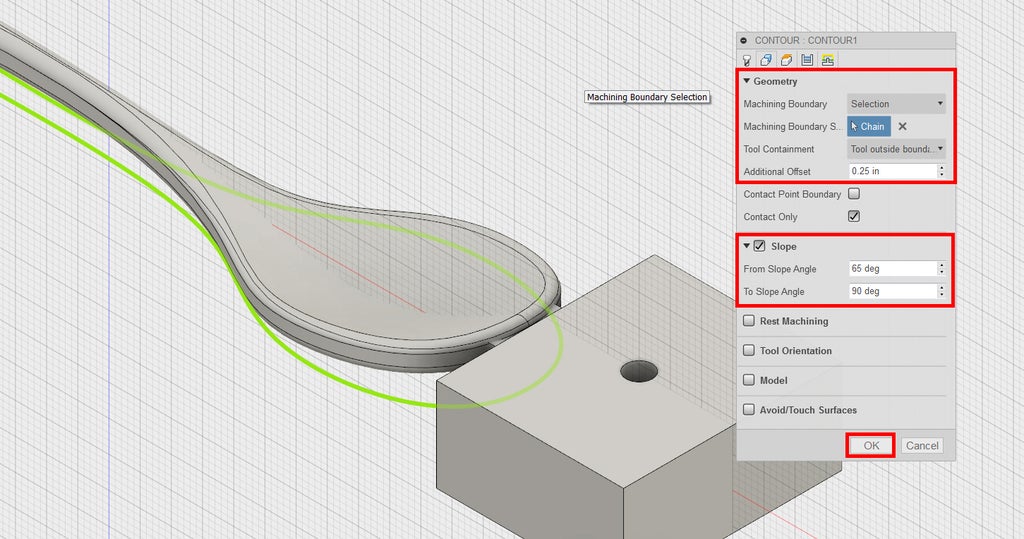
2) Notice the last tool you used is selected by default. This is correct, so click the Geometry tab.
3) Next to Machining Boundary, choose Selection.
4) Carefully click on the same contour you selected for the Parallel toolpath--the contour that runs around the edge of the spoon.
5) Next to Tool Containment, choose Tool Outside Boundary, with an Additional Offset of 0.25.
This will allow the tool to enter the toolpath from the sides, rather than from the top.
6) Check the box next to Slope.
You are going to constrain the toolpath to steeper areas of the geometry.
7) Change From Slope Angle to 65 degrees.
8) Click OK to generate toolpath.
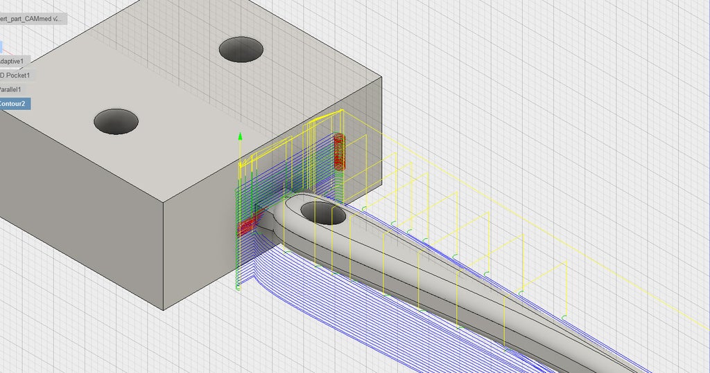
Look at the Contour toolpath. Notice that by default, the tool will helix to lead into the toolpath. You've already machined this area, so you'll want to edit this toolpath, change your heights, and remove the helix. You'll learn how to do this in the next step.
Step 1: 3D Contour Editing
1) Right click Contour1 and choose Edit.
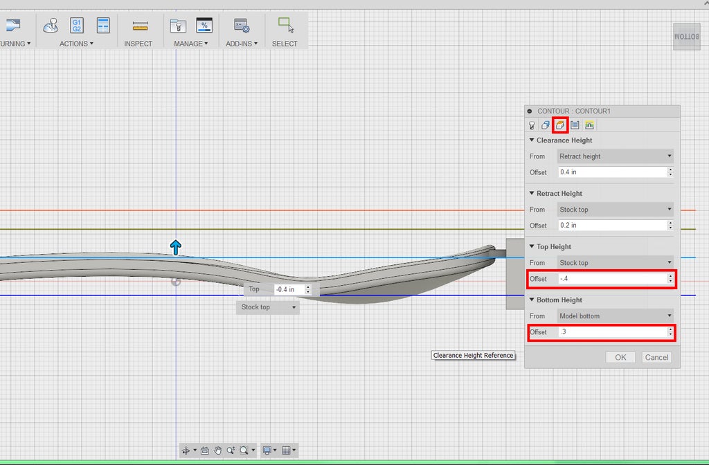
2) Click on the Heights tab.
3) Viewing the spoon from the side, under Top Height, enter an Offset of -0.4.
This will offset the top height 0.4" below the top of the stock. You can see the light blue line corresponding to top height just above the top edge of the spoon.
4) Under Bottom Height, enter an Offset of 0.3.
This will offset the bottom height 0.3" above the model bottom. You can see the dark blue line corresponding to bottom height just touching the lowest part of the bottom edge of the spoon.
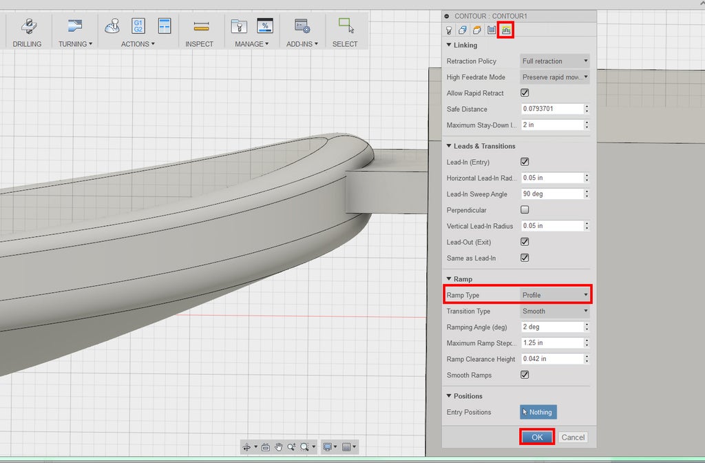
5) Click the Linking tab.
6) Under Ramp, change Ramp Type to Profile.
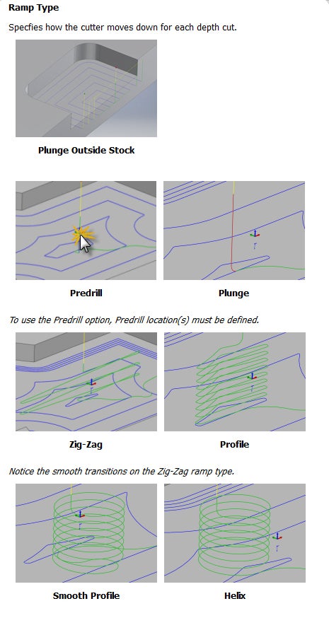
Hover your mouse to read about the ramp types. Profile ramps follow the profile of your part. This will save time and make a smoother toolpath.
7) Click OK to generate toolpath.
Step 2: Simulation Crash and Correction
1) Click Setup 1.
2) In the ribbon, click Simulate.

3) Press Play.
There's another collision--Rapid Collision with Stock. This sometimes occurs when the tool is first descending into a 3D toolpath, as it is here. This means that the tool is moving at rapid speed, which is meant only for non-cutting moves, into your stock. This would break the cutter.
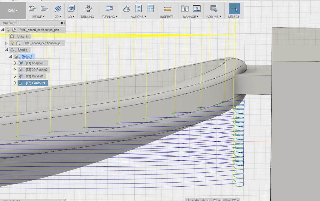
4) Close the simulation, and inspect the toolpath from the side by clicking on Contour1 in the browser tree on the left.
Look especially where the tool enters material. Remember the color codes for the different parts of the toolpath:
Blue = The toolpath itself. The tool moves at the cutting feedrate.
Yellow = Positioning moves. The tool moves at rapid or high speed.
Green = Lead-in/lead-out. This is how the tool moves right before or after each cutting move. You'll notice that the tool moves along the yellow line, at rapid speed, at a height that's just slightly above toolpath itself, meaning that your tool is moving too fast into stock. The green line--the lead-in--needs to be elevated higher so that the tool slows down before cutting. During the lead-in, the tool moves at the lead-in rate, which is much slower than the rapid speed.
5) Right click Contour1, and choose Edit.
6) Click on the Linking tab.

7) Change Safe Distance to 0.2.
Safe Distance is the minimum distance between the tool and the part surface during positioning moves. This prevents the tool from moving at rapid speed too close to the part. When you increase Safe Distance, the size of your green lead-ins also increases.
Usually, the default Safe Distance setting can be left alone, but with more complex 3D parts, there is more likelihood that the Safe Distance needs to be changed to a more conservative number.
8) Click OK to generate toolpath.
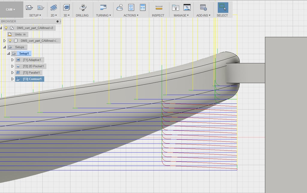
9) Inspect the toolpath from the side again. Note that the green lead-in now begins higher up in Z. There is also now a series of red ramps that slow the tool down as it moves down in Z.
10) Click Setup 1 and then Simulate.

11) Confirm that there are no more collisions. The 3D Contour has nicely finished the sides of the spoon. Close out of the simulation.


