

Introduction: 3D POV Clock From a HDD


In this Instructable we are going to convert an old HDD into a 3D Persistence of Vision Clock.
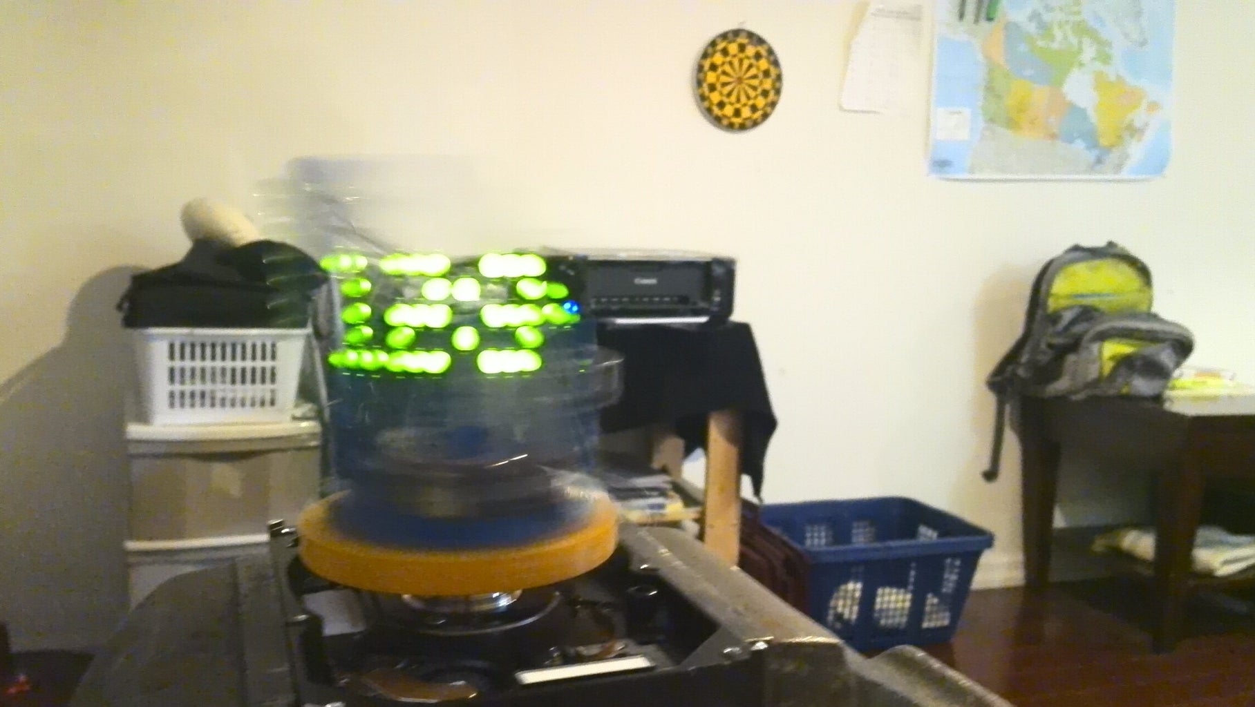
POV Clocks use a simple method to display time in a really neat way. A POV Clock spins a set of LEDs really fast, generally over 800rpm. The LEDs are flashed in a series of arrangements. Our brain recognizes the pattern of flashes and forms an image.
Most of the parts needed for this Instructable can be found in old electronics!
We will be using an Arduino as the brain of our clock.
I recommend going through the Instructable entirely before starting the project.
*The video's high frame rate makes it easy to show that the time is displayed one column at a time. Our eyes cannot detect this as well which will make the time look more uniform.*
Step 1: Materials and Tools


Materials
- Arduino Uno
- Wire
- 6-15 LEDs
- 9v battery pack(I made a battery pack from a dead 9v battery)
- White Tape (for the QTI sensor)
- QTI Sensor (http://learn.parallax.com/KickStart/555-27401)
- HDD*
- Power Supply*
- Calliper
- 3D Modelling Software
- Velcro
- Arduino IDE
*Many places have old HDDs and PSUs lying around. I managed to get one from my high school.
Optional
- Access to 3D Printer
- I made the structure of my POV Clock using a 3D Printer. This structure could probably be made just as easily with wood or plastic. I've included the necessary STL files if you plan to use a 3D Printer.
Step 2: How It Works


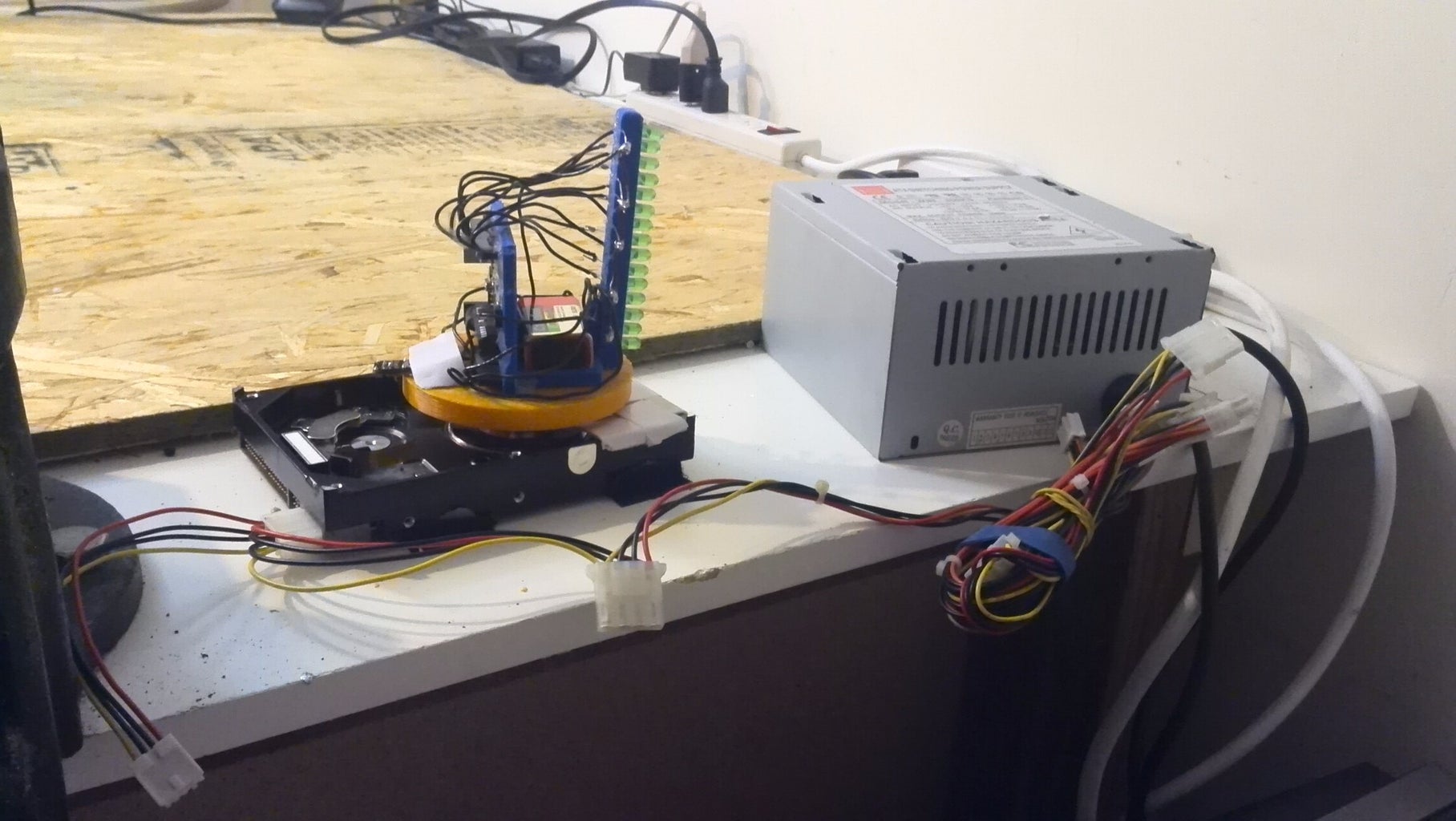
The HDD motor is powered by a PSU. A piece of white tape is attached to the corner of the HDD. Mounted on the motor, are a set of LEDs, an arduino, 9v, and a color sensor. The color sensor is parallel to the piece of white tape. All of these items are spun really fast by the HDD motor. Whenever, the color sensor hovers over the white tape, the arduino flashes the current time, column by column.
Don't worry if you are not completely clear on how the clock works, we'll go into more detail later.
Step 3: Taking Apart the HDD


Disassemble the HDD casing until you can access the HDD motor.
Manufacturers often hide the case screws to prevent tinkering. Looks like that won't pay off :).
Step 4: Getting the HDD Motor to Spin


Now, we're going to get the hard drive motor to spin.
Connect the power supply to the HDD. The motor will not start spinning immediately.
The motor is not receiving any power from the PSU. We can force the PSU to send power to the HDD with one extra wire.
Make sure the PSU is turned off and then connect the green wire, on the motherboard connector, to the adjacent black wire.
Turn the PSU on and watch the motor spin!
Step 5: Make the Structure


We need to build a structure that attaches the clock electronics to the HDD motor hub.
I built my pieces using a 3D printer but you can make them just as easily with wood or foam. Feel free to be original with these pieces since their only requirements is that they hold the electronics. It does not matter if your structure is vaguely similar to mine; your clock will still be very successful.
We need to make 5 pieces for our a clock
- Base
- All of our electronics will be attached to this piece. On my base their is a small hole that the LED Tower inserts into. The battery pack and the arduino mount are glued in place. The base has a ring in the bottom of it's centre. The connector piece fits in this ring.
- Connector Piece
- This piece has 3 holes that attach to the HDD hub. The base rests on top of it.
- LED Tower
- This pieces holds the LEDs in place. The clock only needs 5 LEDs, but the tower can fit 15 LEDs in case we would like to expand.
- Arduino Holder (Optional)
- A holder for the arduino. I got mine off Thingiverse at this link: http://www.thingiverse.com/thing:27759
- Battery Holder (Optional)
- A holder for the 9v battery. I got mine off Thingiverse at this link: http://www.thingiverse.com/thing:336319
I have attached all of the STL and ipt files in case you would like to 3D print your structure.
You probably cannot use my connector piece file for your clock. Your HDD motor hub is probably not the same as my HDD motor hub. If this is the case then we will have to edit the connector piece. Open a 3D modelling software, like Inventor, and start measuring. The diameter of the piece can stay the same but the position of the holes must be changed.


Step 6: Insert LEDs


Insert LEDs into the LED Tower. Only 5 LEDs are required for the POV clock.
Keep all of the positive leads on one side and all of the negative leads on the other.
Step 7: Assemble Structure


Mount the connector piece on the hub with screws.
Insert the LED Tower into the base. Secure the connection with glue.
Place the base on the connector piece. Secure the connection with glue.
Step 8: Mount 9V Battery Pack Holder and Arduino Holder


Mount the 9V battery pack holder and Arduino holder onto the base. I used glue to attach the mounts.
Insert a 9V battery and arduino into the respective mounts.
Step 9: Wire Ground of LEDs


Solder all of the LED grounds to a single wire.
Plug the other end of the wire into the Arduino GND.
Step 10: Mount Switch on Base
Mount your switch on the base with glue.
Step 11: Mount Sensor on Base
Mount the QTI sensor on the base with glue. The QTI sensor should be facing down. Mount a 1 inch strip of tape, parallel to the QTI sensor.
Step 12: Wire the HDD


Wire up the HDD
Attachments
Step 13: Tweaking Your Code

The arduino flashes the current time after the QTI sensor passes over the white tape. We know if the QTI sensor is hovering over the white tape because it will return a particular range of values. These values will be different for every POV clock. Therefore, you must find this threshold for your clock and enter it in the arduino code.
To do this, upload sensorTest.ino to your arduino. Open serial monitor and position the QTI over the white tape. The serial monitor will print out your range of values. Record the most common value.
For my POV Clock, the serial monitor generally printed out the value 100.
After you have your common value, open up hddClockTime2.ino. Scroll down to //EDIT THIS LINE ONLY.
Adjust the threshold until it comfortably includes your common value. Since my common value was 100, I ensured my condition would be true when ls1 is less than 110 and greater than 90. We only want this condition to be true to if the QTI sensor is hovering over the white tape.
Step 14: Test Out Your Clock!

Upload hddClockTime2.ino., power your arduino, and turn your power supply on.
Watch your clock display the current time. If the starting time is not correct, you can change the beginning number of hours and minutes in the arduino code.
Step 15: Velcro Your Clock in Place


Your clock will probably vibrate while its on, so we need to secure it somehow. I ended up velcroing my clock in place. Screwing you clock in place will work just as well.
Step 16: Future
The LED Tower can hold up to 15 LEDs. In the future, I think we can improve the clock and provide more functionality. I am hoping to be able to change the time without opening the Arduino IDE. I am also hoping the clock will be able to differentiate AM and PM eventually.

Participated in the
Before and After Contest

![Tim's Mechanical Spider Leg [LU9685-20CU]](https://content.instructables.com/FFB/5R4I/LVKZ6G6R/FFB5R4ILVKZ6G6R.png?auto=webp&crop=1.2%3A1&frame=1&width=306)


