

Introduction: 3D Printed Cycle


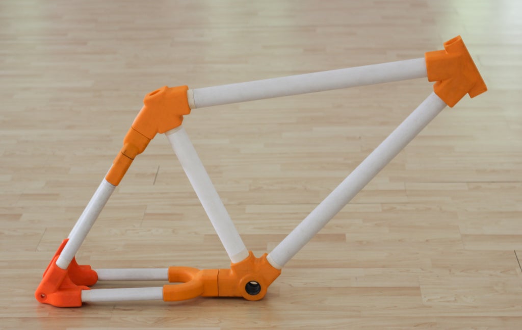
The purpose of this Instructable is to share with the world our experiments in 3D Printing. This Project was done as part of a workshop with my student and good friend Akash Hebbali. We started with the objective of making a full size functioning bicycle that had 3D printed joints that connect PVC pipes to create the frame of the bicycle.
Prior to this project we had worked on much smaller projects with the printer and had limited experience with structural engineering. It was an ambitious project, but to cut a long story short: we failed, the bicycle we created was never able to take the weight of an adult. But, through this project we have learned quite a wealth of knowledge and gained a rather deep understanding of the many technicalities of working with a Prusa i3 FDM based 3D printer and also improved our modelling skills. Up to this project, I have been working with Rhino for 3D modelling, but after seeing how intuitive Fusion 360 is, and its suitability for designing 3D Printed parts I decided to make the switch, and I'm very pleased with the new workflow and experience.
Through this Instructable I hope to guide you through the process of creating a print from concept to assembling the part in your project. The aim here is not for you to make this bicycle and repeat some of the mistakes we made but to learn from them and avoid these mistakes.
Step 1: Design in Fusion 360 for 3D Printing : Philosophy

There are some things you need to keep in my when designing a part that is then going to be 3D printed:
These are some of the simple rules to keep in mind for FDM printers (these are the printers that works on an "additive" principle by laying down material in layers to produce a part.)
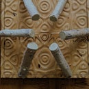
1) Avoid overhangs and Bridges:
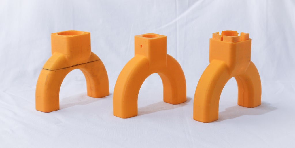
Because all your parts are built layer-by-layer, each layer that is printed must be supported by something underneath it. Features that are not directly supported by underlying layers or the build platform are called unsupported overhangs and examples can be seen in the pictures. Without any supports these features fail to print correctly as seen in picture of the printed part.


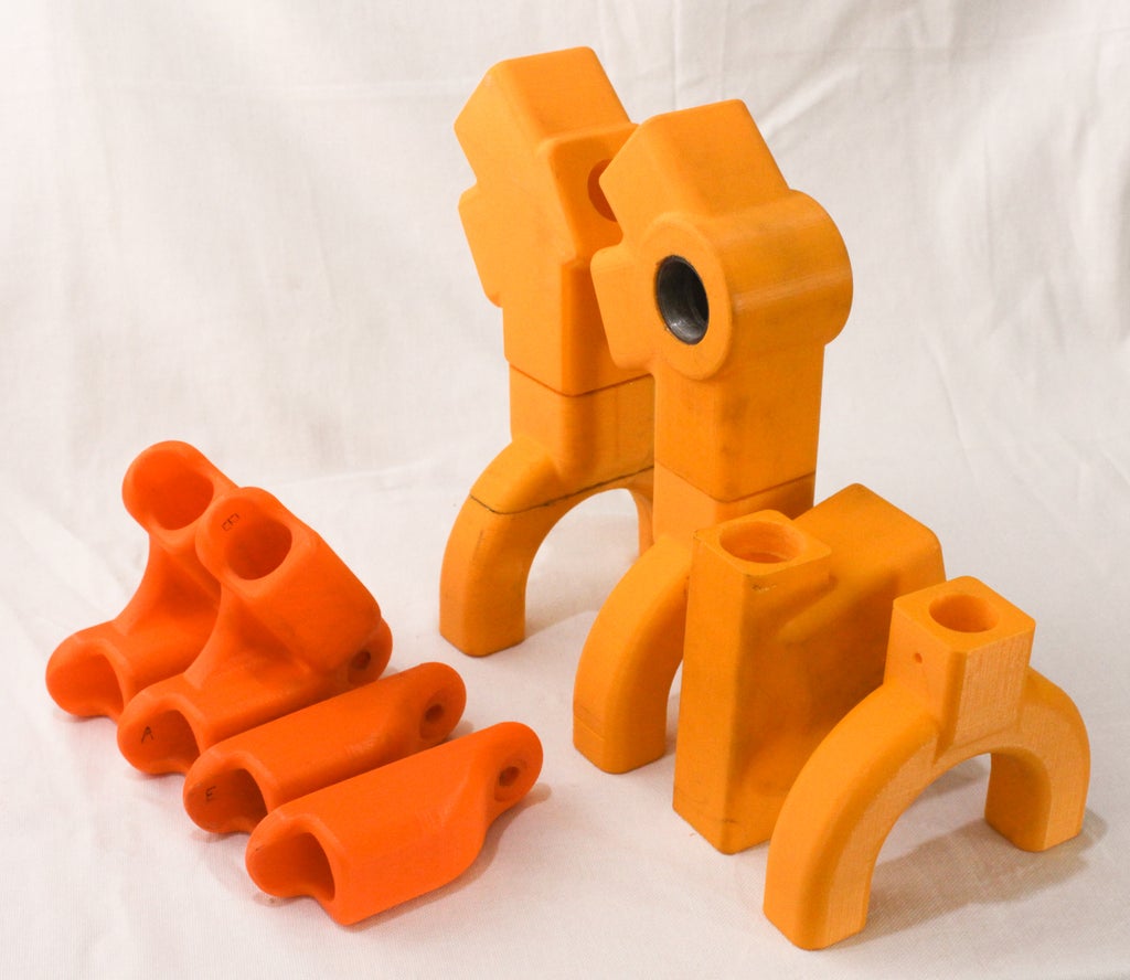
To build these parts successfully, you have to add supports when printing your part. After you receive your part, you can remove the support structures. An example of a 3D printed Dog with supports and rafts and then with the supports and rafts removed can be seen in the Picture.
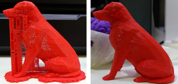
Rafts and Supports are very difficult to remove and so it is recommended to not use them unless absolutely necessary.
2) Part Orientation
Part orientation greatly influences the quality and the material properties of parts like its overall stregth. Like the grain in wood, 3D prints have layers, and they are likely to break along these layers if subjected to high stress.
So if you need high strength in a part then make sure that the layers dont line up with the axis of force that will be applied on the print.

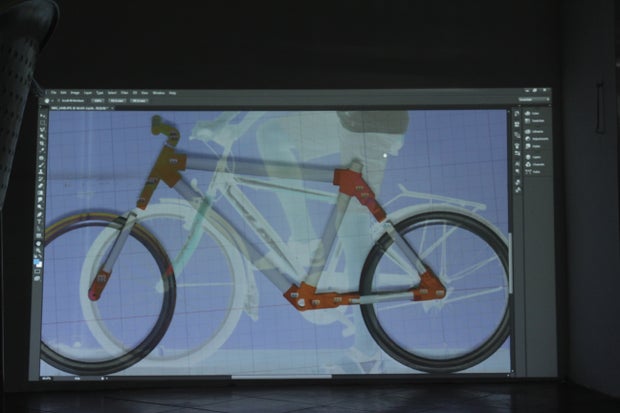
3) Ergonomics:
Ergonomics is the study of people's efficiency in their working environment, or put simply it is designing for comfort. Especially when making a large project it's important to make sure you've got all your dimensions and proportions right. A simple way to check is to use a projector to project at life size your project so that you can get a full idea of scale.


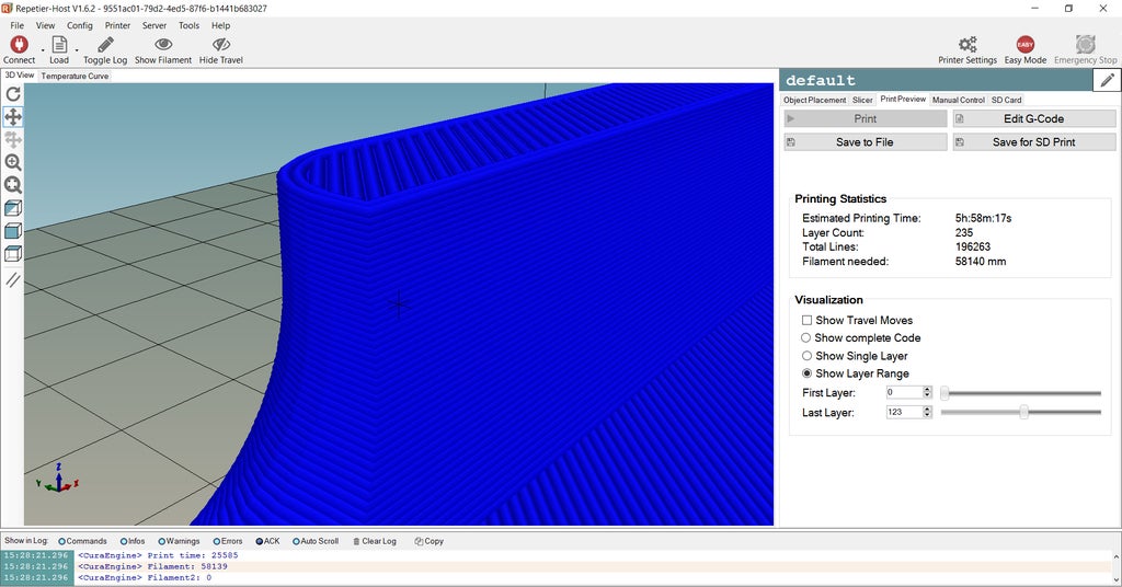
Step 2: Slicing and G-Code Creation

Here I give you some tips on effective slicing for your printer. I'm using Repetier host to generate my G- Code.
Positioning the part on the build plate:
Center parts on the build surface: The closer a part is to the center of the build plate the less it will warp because the build surface is leveled most accurately at its center. In addition, the heated build surface is cooler on the edges which increases warping near the edge.Place parts directly on the platform: Make sure that the part is positioned on the build plate itself. When parts are positioned close together on the build platform, the printer head can move more quickly between parts, reducing build time. Arranging parts too close together can ruin multiple parts if one of the parts detaches. Parts should be placed 5-15 mm apart.
WARNING: Building multiple parts in the same build can cause other parts to print incorrectly if one of the part fails to print correctly. It is best to limit the number of parts per build and submit multiple jobs.Selecting an appropriate orientation: Because 3D printers print parts layer-by-layer, the parts are weakest in the Z axis because layers can sometimes separate from one another. Also, the interior of parts are filled with a 10% dense honeycomb to reduce material use and build time, which also effects the material properties of parts.
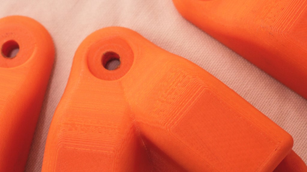
Avoiding stair-stepping: Place curves or sloped surfaces so that they are printed in the XY plane. Curves printed in other planes have a stair-stepping effect. This stair-stepping effect can most easily be seen in parts with really shallow angles as shown in the picture below. Avoid tall, thin features: Parts with small surfaces areas attached to the build surface are likely to become detached during printing due to the forces and moments exerted on them by the printer head. The taller the part, the larger the moments (or torques) it will experience at its base, which means the more likely it will detach while printing.

Step 3: Print + Useful Tips!

Here I list some useful tips that we picked up along the way:
Set the printer to preheat as soon as you are done slicing your model so that you dont have to wait for the printer to reach it's target temperature. Block the airway of the extruder fan if the printer struggles to reach the target temperature, this way you will immediately gain a spike of a couple of degrees that should let the printer start the job.
When printing large flat prints remember to add a little notch or make sure the design has an edge where you could insert a tool to lift your print.
Masking tape works almost as well as painter's tape and is a lot cheaper, you can easily use it as a substitute to cover your heated bed.
When changing filament, snip the end of the filament at an angle for easy insertion into the extruder.
A 1kg roll of filament usually contains 300 meters of the stuff, everytime you slice a print keep a log of how much filament you are using so that when you need to make a large print you can have the peace of mind of knowing that there is enough filament to finish the print.
Do not set up several large print at the same time if you are in a region where there is a chance of a power cut.
Step 4: Assemble and Finish


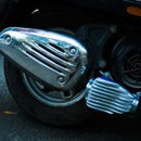
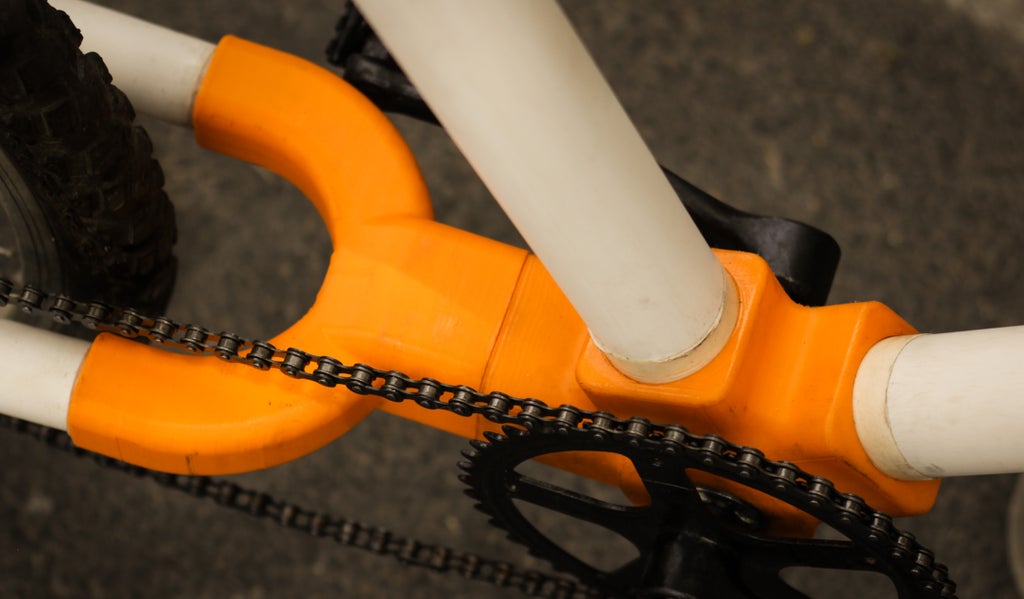
For our project we used some epoxy to seal the pcv pipes to our prints. We also put in some metal inserts where we thought this was necessary, especially at the pedal hub. We also added ball bearing so that the handle bar could spin freely.
Though this project did not produce a functioning bicycle, it did teach us about the many intricacies of operating a 3D Printer and also familiarised us with 3D modelling on Fusion 360. It was therefore a successful learning endeavour for both me and my student. I hope you find it inspiring and can gain something from this instructable.


Participated in the
Design Now: 3D Design Contest 2016

Participated in the
Epilog Contest 8


