

Introduction: Recover Exhaust Energy


While the world is making the evolution towards cleaner and greener
sources of transportation, we still have some years to go before making a full transition to these technologies. Even then it would take most of the world some further years to catch up to those innovations. Here we present a small device that could radically change the efficiency of conventional engines until that time comes.
The efficiency of the modern internal combustion engine that you’d find in an average car or motor bike is at a meager 18-20%. That is most of the energy is lost as waste heat. In other words 4/5 of the energy you put into your vehicle is lost to the surrounding environment. Our device harnesses this waste energy by using a thermoelectric element called a Seebeck module. A Seebeck module uses a difference in temperature to generate electricity (more on this later). We calculated our devices efficiency to be at 3%, Now whereas this may not sound incredible at first glance, look at it this way: our device attached to a vehicle effectively harnesses 3% of the heat energy it encounters. At present our device is designed to attach to the exhaust of a motorbike but it can be easily adapted to that of a car. The amount of waste energy at the exhaust is at approx 60% of the total waste heat of the engine. This means there is an effective increase of efficiency of your engine by nearly 1.3%!
Our device attaches to the exhaust pipe and charges a portable battery, which in turn can be used to charge a phone. Imagine this: if every single owner of a vehicle used this simple device to charge their cell phones while commuting everyday, that would be a near one billion cellphones charged outside the electrical grid which is for now heavily dependent on fossil fuels.
So not only can you charge your cellphone for free you will also be relieving the environment of greenhouse gas emissions from power plants.
So! Lets make some green energy!
If you like our tutorial please do vote for us!

Step 1: Heat Transfer Block

The heat transfer block is what fits the device onto the exhaust of
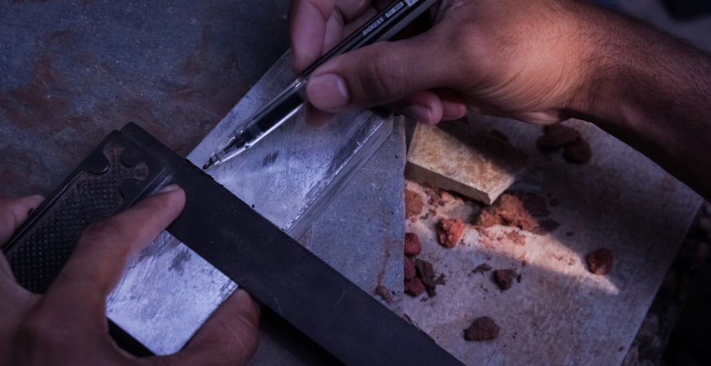
the vehicle. This means optimizing the heat transfer from a cylindrical surface to the flat surface of a Seebeck Module. Measure the diameter of your exhaust. In our case the diameter required was 2.2cm, but this measurement will vary from vehicle to vehicle (especially from a two wheeler to a car).
Since we are using 3 Seebeck modules we need to cover an area of 12x4 cm ( each modules dimensions are 4cm x 4cm )
We started with a block of aluminum 12x4cm which we cut in half.
Then we held them back to back and attached them into a lathe.
Attaching a stationary drill bit on the other end we drilled a hole with a drill bit of a slightly smaller diameter than we required followed by the actual size (this is simply to reduce strain on the lathe).

When take them out and line the two pieces end on end there is have a channel running across the pieces that fits perfectly onto the exhaust.
The heat transfer block is ready!
Step 2: Electronics


We first heard about Seebeck modules when we saw a
project on instructables about a Peltier fridge. It immediately struck us that Seebeck modules had tremendous potential in the field of green energy, but that it hadn’t been used to a great extent. A Seebeck Module basically uses a difference in temperature across it to generate an electric current. For more information on how this effect works check out this link…
Seebeck Modules have a hot side and a cold side, remember to keep the three units the same side up when you solder them in series. (you can quickly test which side is hot or cold by hooking them up one by one to a 9 V battery, after a few seconds you should be able to tell the difference in temperature on opposite sides)
Step 3: Parametric Modeling for the Heatsink.


Spreadsheets help to solve specific mathematical problems- you
start with known and intentionally chosen values impose certain rules upon the system, and then almost beautifully are able to obtain complex results, which further can be immediately recalculated by simply tweaking the original parameters. Parametric design is the geometric equivalent of this process. The benefits are immediate. It's a huge leap in the quality of the design process. It means you are no longer bound by rigid tools because they are malleable to whatever design our our creativity is able to imagine. Parametric design also is fundamental when it comes to minimizing the effort needed to create and test design variants. We wanted a design that was not only optimal to the function of dissipating heat, but also blended aesthetically with the curves of our motorbike- the best tools available to our knowledge was parametric modeling using Grasshopper for Rhino. Using the available library we were able to create a model that merged aesthetics with the limitations of functionality, and then tweaked the the inputs tell we were satisfied we had the best of both worlds.


Step 4: The Heat Sink

Learning about traditional heat sinks online we quickly found them to be function specific.That means heat sinks are designed to suit their particular device but don't have a any kind of basic standard.
So we decided to design one that would suit our scientific and aesthetic requirements. After some research and lots of models we came up with an optimal and elegant design.
For our heat-sink we used two kinds of aluminum extrusions: 3x50mm and 6x20mm we needed around 4 feet of both.
We started by using a hacksaw to cut the extrusions to lengths required by our parametric model.

We then cut out printed templates and glued them onto the pieces.

Next we used a fretsaw to cut out the profiles and polished the pieces with an angle grinder.

The next step was to drill holes into the pieces so that they could be sandwiched together. To make sure all the holes lined up, we clamped the pieces together and drilled through the whole stack. Remember to use some water as a lubricant and coolant since you’ll be drilling into essentially what is a thick block of aluminum which will become very hot!


 Once all the profiles are ready, start the assembly by sliding the profiles into the bolts in the correct order one by one. Tighten the two nuts only after you are sure that all the pieces are aligned so that the back is flat.


It's now time for some heavy grinding, so go get your eye protection!
Trace out the profile with a marker and mount the coarsest metal grinding disk you can find onto an angle grinder.
Proceed with firm curving strokes and stop once in a while to let the heat sink cool down a bit.

Since we did not like the protruding nuts and bolts we mixed up some metal paste to covered them up. We then ground them down to match the flow of the curves.
Step 5: Test Run

We used a digital thermometer to measure the temperature of the exhaust pipe, 250 C. We simulated this temperature in our test run using the flame from an alcohol lamp and regulating the temperature of the heat transfer block. We placed the Seebecks on the block, since this was simply a trial run we didn't use any thermal paste at this point. Then we put on our heat sink and the readings on the volt meter we had hooked up shot up instantaneously! It was super exciting, we reached of 5.1V without air flow, and shot to 6V when we blew through it. The current was measured at 520mA. It was interesting to see how sensitive the Seebeck units were to slight changes in air flow. Mission successful! Time to seal the module with thermal paste and mount it on the motorbike!
Step 6: Assembly

We cleaned the parts and finished minor aesthetic touch ups
before applying a thin layer of thermal paste on each side of the Seebeck's (remember which is the hot side and cold side) and sandwiching them with the heat transfer block on the hot side, and the heat sink on the cold side. We added a few drips of super glue to to the edges to keep the block in one piece for the mounting.


The easiest way to mount this, is to first loop the hose clamps around the exhaust, slide the module into them, and then tighten up.

We ran, and advise you to run the wiring in such a way that it doesn't come into contact with the exhaust. It worked out neatly on this Vespa scooter to remove the plastic storage bin beneath the seat, run the wiring through the guts of the bikes body and replace the bin. Plug in your voltage regulated power bank and it's ready to roll! ( we used a voltage regulated power bank because we had one lying around, but it's easy enough to add your own voltage regulator to the circuitry)
Step 7: Conclusion

This waste heat generator was a success; after the first morning we drove around on the Vespa scooter both our cellphones were charged. Overall this project was an awesome experience, and like with most projects taking something from the drawing board to reality was extremely satisfying. We learnt much on the way and had a blast creating, making and documenting our experience.
Vote for us if you had fun too. :)
Bill of materials:
One aluminum block 12x4x1.5cm
4ft of 3x50mm and 6x20mm aluminum extrusion.
3 Seebeck modules.
One USB cable
Electric tape
Two hose clamps
Two long nuts and bolts
Metal paste
Tools : Hacksaw, Clamps, Drill press, Lathe, Angle grinder, Fretsaw, Screw driver, File, Soldering iron, Scissors.

Participated in the
MAKE ENERGY: A US-Mexico Innovation Challenge

Participated in the
Tools Contest

Participated in the
Explore Science Contest


