

Introduction: A Different Ball Turning Jig for Taig Lathe


I have a small Taig lathe. One of the first things I want to turn is a ball, be it for a drawer or closet door, or for a jig handle. I have viewed some ball turning jigs on the net, and have actually built one of traditional design. The result was less than satisfactory; the rotating platform has a big footprint and the tool-holder tends to get in the way making it difficult to secure the workpiece close to the chuck; the platform spindle is not a tight fit resulting in chatter, and the tool is difficult to adjust to the correct ball diameter. The poor performance is half due to basic design and half due to my rather clumsy workmanship.
Then I come across a rather unique and ingenious design first published in 1994, which I immencely like and wish to replicate. Unfortunately I cannot find any plans, and the author of the video has not given any information on how it is made. Having viewed the video a number of times, I figured out how it works and have succeeded in reverse engineering the jig. My implementation may not look the same but the mechanism, as far as I can judge, works in the same manner. Although it looks complicated, this jig is not difficult to make, quite easy to set up and use, and turns out balls beautifully.
I would like to share my experience with you.
Step 1: How It Works

My jig is based on a YouTube video https://www.youtube.com/watch?v=DIquAgurwC0 posted by Walter Maisey on Nov 28, 2013. According to him this tool was printed in the Model Engineer Workshop Magazine Nov/Dec of 1994, and was designed by Phil Thomas of Booragoon South Western Australia. The video shows a copy made by the author being used to turn a ball, but provides no other information on how it works or how it is made. I cannot find the original article or any relevant plans despite searching extensively on the internet. So I viewed the video many times, and managed to figure out how it works, allowing me to reverse engineer the jig with the same working result.
A ball turning jig has three basic elements. First, it has a platform or other contraption rotating around an axis mounted on the cross slide; second, a tool post mounted at the perimeter of the platform; and third, some means of adjusting the tool bit for a given diameter of the target ball to be turned. Conventional designs usually has a large disk for the platform and the tool bit has to be preset for each intended diameter. The cross slide is locked along the lathe bed and is moved inwards to gradually allow the workpiece to be turned to size. This type of design has a big footprint requiring the work piece to be extended some distance away from the chuck to allow enough clearance for the cutting tool to reach the left hand side or base of the sphere being turned, and the target ball can only be cut to the preset size once it is set.
The design shown in the YouTube video has a small rectangular rotating platform attached to the cross slide. The cross slide remains locked in both x and y positions. The tool post is mounted to one side and may be rotated. The tip of the tool bit marks out an arc following the rotation of the tool post. Its distance from the platform centre determines the radius of the sphere being turned. The tool post is locked onto the platform after the desired radius is set, and the whole platform is rotated to execute the cutting action. The cutting tool is mounted almost tangentially to the surface of the target sphere. The rotation of the tool holder is adjusted with an arrangement of a long screw and hinged nuts.
The advantages of this alternative design are obvious. The jig has a much smaller footprint. This means that the jig on the cross slide can be positioned much closer to the chuck, minimizing flexing of the workpiece at the unsupported end. The tip of the tool can also reach almost into the left side or bottom of the workpiece without interfering with the chuck jaws. It can also be continuously adjusted to closer to or further away from the workpiece so that there is no need to preset the tool for any given diameter of the target ball. Furthermore, because the cross slide is locked during turning operation but the cutting diameter is continuously adjustable, there is no need to half guess when the ball is completed and not over-cut which may result in an ogive instead of a sphere.
Step 2: General Design and Materials

This is a second attempt at making a good ball turning tool. The first one was based on conventional design, but this new design is based on the Thomas model.
I have no facility to mill a rectangular piece with an offset pivot hole in it, and the chuck is not big enough for me to do so on the lathe. I cannot simply copy the Thomas design even if I have the plans. I therefore opt to use an aluminium disk for the platform and attach everything else onto it. I also use a one-piece 6 mm HSS tool piece instead of a reground centre drill mounted on a shank. The end result may look rather different and somewhat complicated but functionally it works in the same way.
Without any reference plans, I made multiple sets of cardboard and foam cutouts and assembled them into dummy setups in different configurations. Eventually I arrived at a workable arrangement which solved the problems of maximizing the size of the workpiece, giving enough travel for the tool tip, preventing moving parts interfering with one another, and optimizing the placement of the pivots.
I then designed the various parts of the jig which consists of:
1. The rotating platform which attaches to the cross slide;
2. The rotatable tool post which is mounted onto the rotating platform;
3. The adjustment mechanism for rotating the tool post, hence adjusting the cutting diameter.
4. A gauge to allow the jig to be aligned precisely.
As I have said in another Instructable I prefer metric units which will be used mostly throughout this article. However in certain areas I have to mix units for the sake of expediency, availabity of materials, drills, dies and taps. For consistency I use the Taig common size of #10-32 for screws and nuts whenever possible. I hope this is not confusing to you.
I must assume that if you are following this article, you are already quite familiar with drilling, threading and tapping as well as basic lathe operations, so I shall not go into any details on these.
Materials
The following materials are used. Wherever possible I use recycled materials or items I find in my junk box.
1. Aluminium disk about 60 mm in diameter 30 mm thick (recycled from extrusion cutoffs, cans etc. molten in my home furnace and recast into ingots);
2. Aluminium cube about 40 mm each side;
3. 2x 626Z sealed ball bearings, measuring 19 mm outside, 6 mm inside diameter, 6 mm thick.
4. 6.35 mm (1/4") steel bolt 50 mm long;
5. 2x 4 mm set screws, 8 mm long;
6. 2x #10-32 cap screws, 3/4" long;
7. 6 mm square section HSS tool blank, 50 mm long;
8. 4 mm screw, 50 mm long (threaded from a 4 mm steel rod recycled from printer);
9. M4 knurled knob 8 mm x 8 mm (recycled);
10. M4 nut and washer;
11. M4 cap screw, 20 mm long;
12. M4 nylon or plastic washer;
13. M6 thin washer, 16 mm diameter (made from one dime coin);
14. M6 cap screw bolt 30 mm;
15. Square nut #10-32 (reused Taig spare part);
16. #10 washer 1.5 mm thick (reused Taig spare part);
17. 4 mm steel rod, about 80 mm long (recycled);
18. 6 mm steel rod, some 50 mm long (recycled);
19. 8 mm steel rod, some 30 mm long (recycled);
20. 12 mm steel rod, some 50 mm long (recycled);
21. 12 mm steel ball tapped #10-32 (for handle bar, turned with this jig);
22. 3 mm steel rod, 30 mm long (recycled);
23. Loctite blue;
24. Plumber's solder.
25. For the gauge, long hex nut for 1/2" screw;
26. For the gauge, #10-32 screw 3/4" long.
Step 3: Design of the Platform

The platform rotates on an axle attached to the cross slide, allowing the tool to rotate with it and cut a circular contour in the workpiece. The platform needs to rotate freely yet stiffly without play. When I made my first conventional jig I used a single 10x26x8 mm ball bearing to provide a rotational axis. This turned out to be a failure because the play of the bearing inner cylinder contributed to wobbling of the platform resulting in chatter, poor dimensional stability and poor surface finish.
The platform is 52 mm in diameter rotating on two stacked 626Z ball bearings pressed fit and locked in place with 4 mm set screws. With two bearings, any play in one bearing is cancelled out by the other. To accommodate two bearings stacked one on top of the other, the platform has to be 12 mm thick. A thin washer, approximately 0.5 to 1 mm in thickness on the axle nut keeps the bottom of the platform from rubbing against the cross slide and seizing up. The axle cap screw head takes up 5 mm. Together, the platform takes up 18 mm of the height between the cross slide and the centre of rotation of the workpiece. The rotational axis of the headstock stands 31 mm above the cross slide. This means that the maximum radius of the ball that can be turned is 13 mm. In other words, a ball up to about 1 inch in diameter can be turned on this jig.
A 6 mm spindle is installed at a position at the perimeter on top of the platform, 20.5 mm from centre. This is the pivot around which the tool post rotates. The position of this spindle is critical and should not be changed.
A barrel nut cage is attached on the rim of the platform. This is part of the tool post adjustment mechanism. The positioning and alignment of this cage is somewhat intricate. See below for further details.
A handle bar is attached to the rim about 15° to the left of the tool post spindle. The exact position is not important, although it should be somewhere convenient and does not intrude into the chuck turning space.
The platform is secured onto the cross slide with an M6 cap screw cut to 18 mm in length and threaded #10-32 for 6 mm at the tip. I turned down the head from 6 mm to 5 mm so that it does not take up more unnecessary room. A #10-32 square nut engages the T-slot in the cross side.
Step 4: Design of the Tool Post and Bit Profile

The tool post is similar to the Taig factory supplied one. It is a block 30 mm tall, 25 mm by 25 mm in cross section. It has a 6 mm spindle hole drilled 6 mm from the edge facing the platform axle, 12.5 mm from either side. Two cap screws lock down the tool bit which is housed in a 6 mm by 8 mm tool slot milled into one side. Another 4 mm hole is drilled 6 mm by 6 mm in the far lower corner to accept an M4 screw attached to a barrow nut as a linking hinge for the adjustment mechanism. This hole is widened to 8 mm and recess at the top to a depth of 10 mm. All dimensions, particularly the hole placements, are critical and should not be changed.
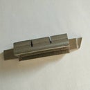
The tool bit is ground from a 6 mm x 6 mm HSS blank, about 50 mm long. The tip is 40° skewed with a 20° relief ground behind the nose on the right. This is arrived at by trial and error, after experimenting with several different profiles. It may not be the optimal one but it cuts well.
Step 5: Design of the Adjustment Mechanism

The tool post is rotated by means of a 4 mm lead screw. This screw, 50 mm long, has a knurled knob attached to one end, and screws into a threaded barrow nut at the other end. The knurled knob end is fed through a barrow nut without threads within a cage attached to the platform rim. The cage is slotted 4 mm high and 8 mm wide on both sides to allow the lead screw to pass through. An M4 nut with washer, secured with loctite, restrains the knurled knob end from sliding away from position when the lead screw is turned.
The barrow nut, into which the lead screw is threaded, is hinged onto the tool holder by means of an M4 cap screw through the body of the tool post. Both barrow nuts are therefore not fixed. As the lead screw is turned they swivel slightly to allow the lead screw to turn freely and not bind.
Turning the screw clockwise rotates the tool post away from the workpiece, giving a larger cutting diameter, while turning counterclockwise gives a smaller cutting diameter. The length of travel of the screw sets a cutting diameter between 0 and 37 mm. After setting to the desired position, the tool post is locked onto the platform by tightening the handle nut.
Step 6: Design of the Gauge for Setting Up Alignments

In use, this jig needs three critical alignments. First, the tool only cuts a circular contour of the right radius if the arc traced out by the tip cuts across the centre of the platform, or axle centre. Second, the axle centre must be lined up with the headstock rotational centre for a perfect sphere to be cut. Third, the centre of the target sphere must align with the axle centre. It is not possible just to eyeball all these alignments. So a gauge is made to show where the axle centre is located and allow precise alignment. A 2" long hex nut for a 1/2" screw is cut to 1" long and machined to slip over the locking cap screw of the platform. A #10 screw with a tapered point is screwed into its wall 18 mm up on one side, with the tip protruding right over the centre of the axle. Half of the nut is cut away above 12 mm to expose the tip of this screw. The uncut half of the nut protects the tip from damage from knocking against other objects in the tool box. This gauge is straight forward and simple to make so I will not go into further detail on its construction.
Step 7: Constructing the Platform


I have a DIY furnace with which I have earlier molten down scrap aluminium and cast into cupcake size ingots for later use. One ingot is about 60 mm in diameter, 30 mm thick. This is the right size for turning into the platform which is 52 mm in diameter, 12 mm thick.
In order to make the ingot manageable for turning, I firstly drilled a 5/16" hole through the middle and tapped it 3/8"-24. This then allows the ingot to be screwed onto the chuck arbor. The ingot is first faced on one side, then the other, reducing its thickness to 12 mm. The diameter is also turned down to 52 mm. The resulting disk is taken off the chuck arbor and centered in the three-jaw chuck. The centre hole is then carefully bored to exactly 19 mm.
I drilled and tapped two 4 mm holes, each centred 4 mm from the top and bottom of the platform at the same position, radially from the rim through to the central hole.
I press fitted the two 626Z ball bearings into the central bore, and screwed in two M4 set screws from the side to lock them permanently in place.
On the opposite side of these two set screw holes, 20.5 mm from the platform centre, I drilled a 13/64" hole through the platform from the top, and tapped it to 1/4"-20. I made sure that this hole is drilled square to the platform surface.
I proceeded to make the tool post spindle which is screwed onto the platform. Ideally I should use an M6 bolt. However, M6 bolts have shanks which are smaller than 6 mm, usually about 5.75 mm. To get a 6 mm spindle, I take a 1/4" (6.35 mm) bolt and turned the unthreaded shank down to slightly under 6 mm, say 5.9 mm. This is why I drilled the hole and tapped it for 1/4"-20 in the first place. I shortened the original 1/4"-20 thread to approximately 10 mm. I then cut off the bolt at 38 mm from the thread and turned this end down to 4.6 mm for a length of 10 mm, and threaded it to #10-32. This bolt is screwed into the flatform where the 1/4"-24 hole has been drilled earlier. The pillar now forms a spindle around which the tool post will rotate. To lock down the tool post, a nut with a short cross handle screws onto the top of this spindle. This nut is made from 12 mm steel rod, cut to 15 mm in length, drilled and tapped #10-32 to a depth of 10 mm. An M3 hole is drill across the cylinder at 5 mm from the top. A 24 mm long 3 mm pin is then soldered into this hole leaving equal lengths sticking out from each side of the cylinder.
I also drilled a 5/32" hole, 10 mm deep, from the rim radially into the disk. This is tapped #10-32. A handle bar is made from M4 rod 80 mm long, threaded both ends for #10-32. A small 12 mm steel ball (which I turned with this jig) is screwed in at one end. With a propane torch the rod is heated to red hot and bent 120° roughly in the middle and then screwed onto the platform after it has cooled. The length and angle of the handle bar are not particularly important.
The adjustment mechanism is attached to the platform by means of a cage which accepts a barrow nut. The attachment is a short 6 mm rod threaded to #10-32 at one end. In order that the adjustment screw does not swivel to too acute an angle, the cage is screwed in off centre. The accepting hole is therefore not drilled radially, but away from the platform centre. See the attached diagram for exact dimensions. This hole is drilled 5/32" and tapped #10-32 to a depth of 15 mm, with the entrance widened to 6 mm for 5 mm, to allow a portion of the 6 mm connecting rod to be recessed and concealed.
I take an M6 cap screw, cut it to 18 mm, turned 6 mm from the tip to 4.6 mm and thread it to #10-32. I also trimmed down the height of the head from 6 to 5 mm to save some room. This screw will engage a #10-32 square nut (Taig spare) to secure the platform onto the cross slide when in use. To avoid the bottom of the platform pressing against the top of the cross slide preventing it to be rotated, I use a 0.5 mm, 15 mm diameter washer between the bearing hub and the cross slide. I don't have one available, so I simply made one from a dime. (It is actually cheaper than to buy one.)
Step 8: Constructing the Tool Post


The tool post is made from a block of aluminium. It is first mounted with the four-jaw chuck on the lathe, trued on all six sides and machined to 25 mm wide x 25 mm deep x 30 mm tall. A 6 mm deep 8 mm tall slot is milled into one side of the block with the lower edge measured at 12 mm from the bottom. This accepts a 6 mm x 6 mm tool bit. Two #10-32 holes are threaded on top of the block to accept #10-32 set screws which fasten down the tool bit. These holes are drilled at two convenient points the locations of which are not particularly critical.
Looking down from above, the face of the block where the tool slot is milled, is the LEFT face, and the face on the far side is the FAR face. All the other faces are there oriented accordingly, the RIGHT face opposite the left face, and the NEAR face opposite the FAR face.
A 6 mm hole is drilled 12.5 mm from the left face, and 6 mm from the front face, down through the block. This hole must be drilled absolutely perpendicular to the bottom face. I mounted the block off centre onto the lathe with the four jaw chuck to drill this. This hole will mate with the spindle in the platform and will allow the tool post block to rotate squarely and smoothly.
Finally, a 4 mm hole is drilled, 6 mm from the right face and 6 mm from the near face, through the block. The top 10 mm of this hole is widened to 8 mm. This hole accommodates a 20 mm M4 cap screw which attaches but not tightened to a barrow nut which forms part of the adjustment mechanism.
Step 9: Grinding the Tool Bit

I cut a piece of 6 mm x 6 mm HSS lathe tool stock, approximately 50 mm in length, to make the tool bit for this jig. I have no guidance as to what profile would work. I do not want to fabricate a special tool bit similar to the one used in the Maisey's construction, but I took some inspiration from it. So I experimented with several profiles, firstly juggling with cardboard cutouts, and then grinding a few test pieces. Eventually by trial and error, I arrived at a working profile. This profile has a 40° tip skewed to one side with 20° to the right of the nose but no top relief, the nose leaning in towards the workpiece. The nose is rounded to about 1 mm. The attached photo shows this clearly. I am not sure if this is the best profile, but it seems to work quite well indeed.
Step 10: Constructing the Adjustment Mechanism


The mechanism for adjusting the cutting diameter is a little intricate. It consists of a long lead screw which goes through an unthreaded barrel nut in a cage at one end, and screws through another threaded barrel nut linked to the tool post at the other end. The screw is turned with a knurled knob attached to the cage end, and is confined by a locking nut on the other side of the cage. Both barrel nuts must be allowed to swivel freely while the screw is turned in and out, otherwise the screw will bind at some point.
I found an M4 knurled knob in my junk box so I made an M4 screw to go with it. (If you only has an 1/8" knob, you can use 1/8" screw instead and make the other parts to this dimension.)
I threaded a 50 mm length of 4 mm steel rod to M4 for the lead screw. I screwed the knurled knob to one end and secure in place with loctite.
With a length of 8 mm rod, I cut two cylinders 12 mm long. I made these into barrel nuts. The first I simply drilled a 4 mm hole crosswise through the middle. This is the barrel nut which goes into the cage.
The second, I drilled and tapped an M4 thread to 5 mm through one end, and drilled and tapped an M4 thread across in the middle. This forms the barrel nut linked to the tool post.
I cut a 15 mm length of 6 mm rod and threaded #10-32 for 5 mm at one end. This is the barrel nut cage mounting rod.
I took a 12 mm rod, drilled an 8 mm coaxial end-hole, 12 mm deep and cut it off at 12 mm. I drilled a 6 mm hole through this cylinder from one side in the middle. I then soldered the 6 mm end of the barrel mounting rod into this cross hole and dressed the inside surface smoothly. Then at right angles to the mounting rod, I drilled an M4 hole through the cylinder on both sides. I widened this hole crosswise into a slot about 8 mm wide on both sides. This forms the barrel nut cage. The M4 slot allows the lead screw to pass through the cage and the barrel nut, with room to swivel when the screw is turned.
Step 11: Assembly

The two 626Z ball bearings are inserted and pressed fit into the 19 mm axle hole in the platform. Two M4 set screws are screwed in from the rim to secure the bearings tightly in position.
The 6 mm tool post spindle is screwed onto the platform. The thread is secured with loctite.
The barrel nut cage is screwed into the hole provided. It is turned in until all threads are recessed and concealed. Do not tighten, as the nut needs to swivel slightly. The cage should be installed with its opening perpendicular to the face of the platform. I then inserted the lead screw into the cage and screwed in an M4 nut with a washer from the other end against but not tightly against the cage cylinder. I secured the nut onto the lead screw with locktite. The lead screw is now constrained and will not move out of position.
The tool post is slid onto the spindle. I inserted an M4 x 20 mm cap screw into the M4 hole at the corner of the tool post block, put a thin M4 nylon washer in between and screwed it into the barrow nut from the end. The barrow nut is left in a loose fit and allowed to rotate freely.
I screwed the handle nut onto the spindle, with a #10 washer in between and secured the tool holder in place.
I then put the tool bit in the tool slot and secure it with the set screws from the top.
Finally I screwed in the handle bar and secured its thread with loctite.
The jig is now complete.
Step 12: Calibration and Setting Up


Before the jig can be used, it has to be calibrated. The nose of the tool bit must swing an arc to meet the centre of the platform axle.
To do this, place the gauge onto the platform locking cap screw and turn the tip of the screw taper inwards towards the tool post. Loosen the tool post with the handle nut. Twist the knurled knob to move the tool inwards until the nose of the tool comes close to the gauge screw. Loosen the set screws on the tool bit and slide the tool bit in or out until the nose of the tool bit touches the gauge screw tip. You may need to readjust the knurled knob in order to do this. Once this is achieved, retighten the set screws securing the tool bit. The jig is now properly calibrated.
To use the jig, it is first secured onto the cross slide with the locking screw and square nut provided. The best position to place the jig is towards the far end of the left hand T-slot (viewed from front of lathe). This allows the jig to get closer to the chuck, and leaves room for your fingers to twist and turn the knurled adjustment knob.
Prepare the workpiece by cutting out a cylinder of the desired ball diameter (or slightly larger), firstly drilling and tapping a suitable thread into it from one end. Attach this cylindrical workpiece to a spindle with the correct thread size and tighten securely. If it is not tightened, the cylinder will shift in position as the cutter bears pressure onto it. Mount the workpiece with its spindle onto the chuck, or collet if you prefer, leaving a clearance of about 45 to 50 mm. With a small centre drill in the tail stock, mark a very shallow and tiny centre mark at the end of the workpiece.
As I have mentioned earlier, the jig needs three critical alignments. One is already set up. We need to set the other two.
First, centre with the headstock rotational axis. Place the gauge onto the cap screw securing the jig to the cross slide and turn the screw tip towards the workpiece. Move the cross slide until the gauge screw tip lines up with the centre mark. Leave the cross slide in this position.
Loosen the handle nut on the tool post and widen the cutting diameter of the tool. Eyeball where the centre line of the workpiece might be and move in the slide longitudinally over there. Turn the jig handle to see where the tool tip meets the corners of the workpiece. You may need to readjust the tool cutting diameter for the tip to come close to the corners. If the nose of the tool just touches both the left and right corners of the cylinder then the jig is centred onto the workpiece. Lock the slide onto the bed.
The jig is now set up. The cross slide should remain locked throughout and does not need to be touched.
Step 13: Test and Conclusion


I set up the jig in the manner described and tried cutting several balls in steel. They turn out to be very satisfactory. The diameter of the ball is adjustable on the fly. The cutter moves deeply into the left hand side of the ball without interfering with the chuck. There is no chatter and the balls have very good finish although some touching up with a file and sand paper is needed.
In addition to having a good functioning tool, I also get a nice looking one. I am more than pleased with this project.
I have embedded a video here to show this jig in operation.
Step 14: Epilog: Further Improvements

Now that I have this jig up and running and used it many times, I have made some further improvements.
When I used the original jig as first made I found that the adjustment screw got sticky in certain positions and did not turn very well. This was mainly due to friction of the knurled knob and the restraining nut and washer rubbing against the swivel cage.
To improve this, I turn an 8 mm diameter ball with a M4 through thread. The adjustment screw chain is disassembled and I remove the barrow nut in the cage as well as the restraining nut and washer. The ball nut is then placed in the cage and the long thread is screwed into it through the side slots. The knurled nut is placed 1 mm from the side of the swivel cage, leaving a small gap so that it does not rub against it. The ball nut is secured with loctite so that it will not turn on its thread but will rotate with the knurled nut. The ball nut in the cage restrains the knurled knob from moving off. I then reassembled the adjustment mechanism. The knurled knob now turns very smoothly.
I have also replaced the cross bar in the tightening nut with ball-tipped handles. This modification is more cosmetic than functional.
Finally I reground the tool bit with a deeper hook. This new configuration clears the chips better and works quite well. However, this is only a minor improvement and may not really be necessary.


