

Introduction: ATtiny84/85 SPI Interface Pin Reuse


This instructable is a follow up to the "ATtiny84/85 In-circuit Debugging with Serial Output" instructable and extends that hardware and software configuration to address the issue of reuse of the programming download pins by the application program. Altogether, between this and the part 1 instructable, the following topics are discussed/demonstrated:
| Topic | ATtiny84 | ATtiny85 |
|---|---|---|
| Serial Communication using the SoftwareSerial class | X | X |
| Sharing device pins between application and download | X | X |
| Pin Change interrupt | X | |
| External interrupt | X | |
| Sleep in POWER_DOWN mode; wake on interrupt | X | |
| Work-around for the "multiply defined" interrupt vector link error related to SoftwareSerial | X | |
| In-circuit modify, download, debug, ... development cycle for the ATtiny devices | X | X |
Adding a hardware I/O component to one of the pins dedicated to the SPI programming interface is sometimes OK, sometimes not. For example, adding a LED to MISO just causes the LED to flicker during download and then it is available for the application. However, adding a piezo buzzer to MISO will result in a horrible screeching sound followed by download failure.
This instructable explains how to use a 4x2:1 multiplexer to "recover" use of the pins assigned to the SPI interface MISO, MOSI, and SCK signals by protecting them during download. Reuse of the RESET pin requires a fuse change and is not covered by this approach. Dual assignment of the pins is accomplished by using the multiplexer to switch between the application and programming inputs depending on whether download is in progress. Code and schematics are included for both the ATtiny84 and ATtiny85. The ATiny84 configuration is addressed first since it has two I/O ports and can be used to illustrate some additional problems/solutions. Following the tiny84 discussion, the same scenarios are discussed for the ATtiny85.
Step 1: Required Hardware
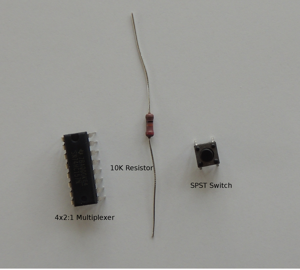
Most of the required hardware was listed in the part 1 instructable so only the new hardware is listed below.
| Name | Possible Source | How Used |
|---|---|---|
| 4x2:1 Multiplexer | Mouser | Contains four 2-input;1-output switches which are the mechanism by which the SPI Interface signals and application I/O's are shared. |
| SPST switch | Any switch type (momentary or latched) will work. The switch is used to illustrate pin sharing for an application input. | |
| 10K resistor | Pull-down resistor for the SPST switch to avoid a floating input |


The multiplexer is the key to isolating pin download use from application use. The overall functionality of the 4x2:1 multiplexer is fairly straight-forward consisting of 2 control signals and 4 identically functioning switches. The behavior of each multiplexer pin is discussed below:
| Pin | Name | Function |
|---|---|---|
| 15 | G | As indicated in the truth table, the multiplexer only functions when the G enable pin is low. Since we never want to totally disable the multiplexer, pin 15 will be connected directly to ground. |
| 2-4; 5-7; 9-11; 12-14 | A(input), B (input), Y(output) | There are four 2-input; 1-output switches with each group of 3 pins numbered consecutively in the order A (input), B (input), Y (output) e.g. for switch 1; pin 2=1A; pin 3=1B; pin 4=1Y. |
| 1 | Select | When Select is low, switch input A is connected to the associated switch output pin, Y. When select is high, switch input B is connected to output instead. The switches are controlled simultaneously by the Select signal and function identically. |
| 8 | GND | multiplexer IC ground |
| 16 | VCC | multiplexer IC power |
Step 2: Overview of Test Cases


The two scenarios for pin reuse are based on whether the pin is an application input or output. The procedure for handling any input is always the same; also the procedure for application outputs is identical regardless of the hardware component. Even so, the explanation is easier, and hopefully clearer, if specific examples are given. Minimalist layouts for the two cases are shown above. For the detailed setups later on the connections become a bit of a squirrels nest so it might be useful to refer back to these cleaner diagrams.
RESET is the perfect choice for the multiplexer Select signal since it is low during download but goes back high when download completes. Note that any of the multiplexer switches could be used for either case since all switches behave identically. Also, neither of the examples is "realistic"; they were chosen instead as the most straightforward way to illustrate the isolation techniques
- Output Case: LED output from ATtiny84 pin 4 (SCK) is isolated using multiplexer switch 2
- connect multiplexer pin 2A to ground
- connect multiplexer pin 2B to ATtiny85 pin 4
- connect output 2Y to the LED anode
- Expected Results:
- LED is off during download since connected to 2A, ground
- LED attached to application output pin 4 after download via 2B and starts to blink
- Expected Results:
- Input Case: SPST switch input to ATtiny84 pin 6 (MOSI) is isolated using multiplexer switch 3
- MOSI lead wire from the AVR Programmer header is moved to 3A
- switch input 3B is connected to SPST output
- output 3Y is connected to ATtiny84 pin 6
- 3A, MOSI, is connected to pin 6 during download
- 3B, SPST output, is connected to pin 6 after download
Case 1 is successful if the LED doesn't flicker during program download and then blinks every two seconds following download as expected under program control. Without isolation the LED would flicker during download since it is connected directly to the SCK signal, which changes state to clock data receive/transmit.
Case 2 is successful if the MOSI signal is forwarded on to the ATtiny84 during download, i.e. download doesn't fail, and the LED responds to SPST switch on/off after download. Case 2 does prevent one unlikely download failure. Without isolation, the SPST switch will cause failure if 1) a latched switch is used and 2) the switch is left in the on position during download. When isolated by the multiplexer, the switch can not cause download failure under any circumstances. A bit of a stretch but comforting for us old folks.
One consequence of using the multiplexer is that the hardware component can no longer be connected directly to the microcontroller I/O pin. This is somewhat inconvenient but does allow the component to remain on the breadboard during test along with the other application hardware, and can be moved back to its rightful location when test is completed.
Step 3: ATtiny84 Case 1 - Isolate Application Output

This step describes setup for sharing of an application output pin with a download signal. The example used is the LED attached to pin 4 (SCK). Using the existing LED as the example allows emphasis on addition of the multiplexer to the part 1 hardware and software environment.
- Hardware
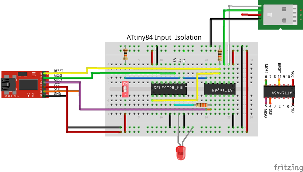
- Add the multiplexer to the breadboard in the relative location shown in the fritzing diagram above. The multiplexer is positioned towards the center to allow room for the SPST switch needed in Case 2.
- Extend the RESET signal to the multiplexer by adding a lead wire (suggest yellow) from ATtiny84 pin 11 to multiplexer pin 1.
- The remaining hardware setup is as given in Step 2
- connect multiplexer pin 2A directly to ground
- connect pin 2B to ATtiny84 pin 4
- connect output 2Y to the LED anode
- Expected Results:
- during download 2Y is connected to ground (2A) so the LED remains off
- After download 2Y is connected to ATtiny84 pin 4 - application LED control
- Expected Results:
- Software
- The part 1 code is reused; available from the part 1 instructable rather than duplicated here
- Load and compile the part 1 program in the Arduino IDE
- Plug in the Tiny AVR programmer to a PC USB port
- Plug in the Adafruit USB to Serial cable to a second USB port
- A COM port is created and is automatically made available in the IDE port list
- Launch the COM window
- Download the compiled code to the ATtiny84
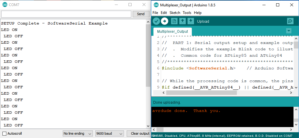
The application program results are the same as for part 1 since the only change was to move the LED to a "protected" location: The LED blinks at 2 second intervals; serial output is the same. The one difference that should occur is that the LED no longer flickers during download since, during that time, it is connected to ground through multiplexer pin 2A.
Step 4: ATtiny84 Case 2 - Isolate Application Input
This step builds on the setup for the previous output isolation case. Hardware changes consist of attaching a SPST switch to ATtiny84 pin 6 (MOSI) via the multiplexer. So the hardware changes are minimal but there are several software changes to allow the SPST switch to control the LED using a pin change interrupt. The updated code is included at the bottom of this section. The code should be copied into the Arduino IDE; suggest saving it under the name Multiplexer_Input. (I apologize for the length of this section but it is the heart of the instructable's purpose and think it reads better as a monolith rather than inserting artificial breaks.)
| Update | Location | Purpose |
|---|---|---|
| include "hacked" SoftwareSerial class | include section | The LED is now controlled by the SPST switch via a pin change interrupt. The SoftwareSerial class must be modified since otherwise it allocates ALL the pin change interrupt vectors. This causes a "multiple definition" link error for the (port 0) vector assigned to the SPST switch. The hacked SoftwareSerial version should be placed in the same directory as the program so that it affects only this application. |
| SPST input pin definition | include/definition section | assignment of SPST input to a device pin. The pin is device specific so it is added to the #ifdef ATtiny8x section(s). |
| SPST input pin mode | setup function | The SPST pin is configured as an INPUT |
| Configure SPST pin interrupt | setup function | The interrupt vector is assigned to the SPST input pin so that a switch state change causes an interrupt. The configuration registers and interrupt type are device specific. To make the code as straightforward as possible, the differences are handled within a #if defined section |
| Setup complete serial message | setup function | The setup complete serial output message is changed to reflect the Multiplexer Input application |
| Add SPST switch ISR function | code section | The ISR for the SPST pin change interrupt is added. The code is common but the vector used is device specific and is defined in the device dependent sections at the top of the program. In order to verify the ISR is activated, the LED state is changed. Although a no-no in a real application, a serial output message is generated reflecting the new LED state. |
| Modify loop processing | loop function | The ISR now controls turning the LED on and off so that functionality is removed from the loop routine. A call to the sleep routine is added for ATtiny84 as sort of an "extra". For this application, ATtiny85 sleep doesn't work; maybe due to the interference of the Software Serial class since it does work with SoftwareSerial removed. |
| Add sleep routine | code section | Sleep functionality is not necessary to demonstrate use of the multiplexer. Just added because would ordinarily want to wait for an input in POWER_DOWN mode to save power rather than continue to run through the program loop doing nothing until an input occurs. |
Modify the SoftwareSerial class Code
The SoftwareSerial class needs to be changed so that it doesn't hog all the pin change interrupt ports. The SoftwareSerial class code is located at
C:\Program Files (x86)\Arduino\hardware\arduino\avr\libraries\SoftwareSerial\src
Do a find on PCINT0_vect in SoftwareSerial.cpp to find the start location for the code changes. Add the following code immediately preceding the existing #if defined(PCINT0_vect) statement.
#if defined(__AVR_ATtiny84__)
#define MYPORT  PCINT1_vect
#elif defined(__AVR_ATtiny85__)
#define MYPORT  PCINT0_vect
#endif

ISR(MYPORT)
{
  SoftwareSerial::handle_interrupt();
}
Now comment out the existing block of code which allocates the port interrupt vectors as indicated below (just add the start and end block comment symbols /* and */):
/*

#if defined(PCINT0_vect)
ISR(PCINT0_vect)
{
  SoftwareSerial::handle_interrupt();
}
#endif

#if defined(PCINT1_vect)
ISR(PCINT1_vect)
{
  //SoftwareSerial::handle_interrupt();
  ISR(PCINT1_vect, ISR_ALIASOF(PCINT0_vect));
}
#endif

#if defined(PCINT2_vect)
ISR(PCINT2_vect, ISR_ALIASOF(PCINT0_vect));
#endif

#if defined(PCINT3_vect)
ISR(PCINT3_vect, ISR_ALIASOF(PCINT0_vect));
#endif

*/
Configure the Hardware
The SPST switch is attached to ATtiny84 pin 6 (MOSI) as outlined in Step 2. The procedure is duplicated here for convenience.
- connect switch input 3A to the Tiny AVR Programmer header MOSI lead
- connect 3B to the SPST switch ON output pin
- connect 3Y to ATtiny84 pin 6
- RESULTS:
- 3A, MOSI, will be gated through to ATtiny84 pin 6 during download
- 3B, SPST output, will be gated to pin 6 after download
- RESULTS:
Run the program
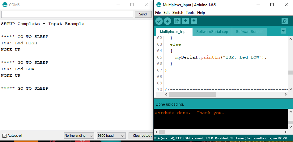
Before running, put the SPST switch in the off position. Otherwise the LED will turn on when the switch is turned off and vice-versa . Follow the procedure for step 3 to load, compile, and download the application input program using the Arduino IDE. As before, the LED should not flicker during download so the only indication that the program is up and running will be the serial message at the end of the setup routine: SETUP Complete - Input Example
At this point the program is waiting for an input from the SPST switch. Placing the switch in the ON position will cause the LED to turn on; changing back to the off position turns the LED off. Output messages verify that the ISR was invoked (ISR: Led HIGH, ISR: Led LOW). Notice the order of the serial messages is GO TO SLEEP first waiting on a switch state change; when get a switch input the ISR is invoked, toggles the LED, and documents the change; then processing picks up following the sleep call since the interrupt wakes up the processor.
PROGRAM FOR THIS INSTRUCTABLE:
//************************************************************************
//  PART 2: Application/download device pin sharing
//  .  Modifies the Part 1 code to support application reuse of the pins
//     assigned to the SPI programming interface
//  .  "Comon" code for ATtiny85 and ATtiny84
//************************************************************************
#include "SoftwareSerial.h"             // Modified Arduino SoftwareSerial class
#include <avr/sleep.h>

// While the processing code is common, the pins used are device specific
#if defined(__AVR_ATtiny84__) || defined(__AVR_ATtiny84A__)
  #define ledPin    4                   // Toggled to turn connected Led on/off
  #define rxPin     9                   // Pin used for Serial receive
  #define txPin     10                  // Pin used for Serial transmit
  #define SpstPin   6                   // Input from SPST switch (MOSI)
  #define ISR_VECT PCINT0_vect          // SPST switch Pin change interrupt vector
#elif defined(__AVR_ATtiny85__)
  #define ledPin    1
  #define rxPin     4
  #define txPin     3
  #define SpstPin   2                   // Input from SPST switch (INT0)
  #define ISR_VECT INT0_vect            // SPST switch Pin change interrupt vector
#else
  #error Only ATiny84 and ATtiny85 are Supported by this Project
#endif

// Create instance of the Software Serial class specifying which device
// pins are to be used for receive and transmit
SoftwareSerial mySerial(rxPin, txPin);

//------------------------------------------------------------------------
// Initialize processing resources
//------------------------------------------------------------------------
void setup()
{
  mySerial.begin(9600);       // Start serial processing
  delay(2000);                // Give Serial Com port time to complete start up.
                              // otherwise, 1st output likely missing or garbled

  pinMode(ledPin, OUTPUT);    // Configure led pin for OUTPUT
  pinMode(SpstPin, INPUT);    // Configure SPST switch pin as an INPUT

#if defined(__AVR_ATtiny84__) || (__AVR_ATtiny84A_)
  // set up pin change interrupt to handle switch input on pin 6 (MOSI)
  GIMSK   |= (1<<PCIE0);             // enable Port 0 (Port A) pin change interrupts
  PCMSK0  |= (1<<PCINT6);            // enable pin change interrupt on pin 6
#elif defined(__AVR_ATtiny85__)
  // set up external interrupt to handle switch input on pin 2 (SCK, INT0)
  MCUCR |= (0<<ISC01)+(1<<ISC00);   // set interrupt mode to CHANGE
  GIMSK |= (1<<INT0);               // enable external interrupt 0
#endif

  mySerial.println("SETUP Complete - Input Example");
}

//----------------------------------------------------------------------------------------------------
//  ISR for SPST switch state change interrupt.  The interrupt vector used is depends on the device
//  and defined in the device dependent defines at the top of the program.
//----------------------------------------------------------------------------------------------------
ISR(ISR_VECT)
{
  digitalWrite(ledPin, !digitalRead(ledPin));
  if(digitalRead(ledPin))
  {
    mySerial.println("ISR: Led HIGH");
  }
  else
  {
    mySerial.println("ISR: Led LOW");
  }
}


//------------------------------------------------------------------------
// The interrupt routine does all the work so nothing to do here
//------------------------------------------------------------------------
void loop()
{
#if defined(__AVR_ATtiny84__) || defined(__AVR_ATtiny84A__)
  goToSleep();
#endif
}

//----------------------------------------------------------------------------------------------------
//  Put processor in POWER-DOWN sleep mode (SPST switch interrupt will awaken)
//----------------------------------------------------------------------------------------------------
void goToSleep()
{
  // Indicate going to sleep
  mySerial.println();
  mySerial.println("***** GO TO SLEEP");

  // Put processor to sleep in POWER DOWN mode
  sleep_enable();                         // enable sleep mode
  set_sleep_mode(SLEEP_MODE_PWR_DOWN);    // set sleep type to POWER DOWN
  sleep_cpu();                            // enter sleep mode. ISR executed when interrupt wakes processor.
  sleep_disable();                        // returns here after interrupt; disable sleep mode

  // Indicate that now awake
  mySerial.println("WOKE UP");
}
Step 5: ATtiny85 Case 1 - Isolate Application Output

Rather than build a duplicate hardware setup for the ATtiny85, it's probably easier to start with the finished configuration for ATtiny84 from Step 4 and replace the tiny84 chip with the tiny85. All the required hardware is then already available. If using this approach, locate the tiny85 so that pins 3 and 4 line up with the serial cable tx and receive wires. It is then just a matter of relocating the SPI interface lead wires to match their required locations for the ATtiny85.
If starting from scratch, just follow the general steps from Step 3 and the fritzing diagram above. The code is the same as used for the ATtiny84 in Step 3 with the same results expected - no flicker during download; when running the LED blinks at 2 second intervals and serial output messages follow the LED state.

Step 6: ATtiny85 Case 2 - Isolate Application Input

For hardware setup, start with the configuration from Step 5 and add the SPST switch as indicated in the fritzing diagram above. I actually used a momentary switch for the tiny85 version and it makes verification a little easier. Notice that the switch output is rotated 180 degrees from the ATtiny84 configuration. This change makes it easier to route the hookup wires since all 3 SPI signals are on the same side for the ATtiny85.
Use the same program as for ATtiny84 Step 4. The same general results are expected - the LED changes state when the SPST switch is turned on/off and serial output messages document the changes. The GO TO SLEEP messages are missing since sleep functionality is not invoked for the ATtiny85. Even though the same program is used, there are significant differences in implementation to account for the fact that the ATtiny85 has only one port register (Port 0):
- SoftwareSerial now allocates the port 0 pin change interrupt for serial communication (Recall that we were able to use port 1 for the ATtiny84.)
- The SPST switch interrupt must be implemented with external interrupt 0 (INT0) since the one and only pin change interrupt is allocated by SoftwareSerial. This does illustrate the point that pin change interrupts and external interrupts are logically independent and can be used within the the same port register.
- Nothing is gained by using a modified SoftwareSerial version - there is only one port and the SoftwareSerial class WILL grab it. However, the modified class was still used just to avoid a change not directly related to the goal of this step.


Participated in the
Microcontroller Contest


