Introduction: ATtiny84/85 In-circuit Debugging Using Serial Output
Like a lot of other people, I got started in the Arduino world with the UNO and then moved on to the ATtiny84 and ATtiny85. While development on the ATtiny devices is interesting (and addictive), there are a couple of serious drawbacks related to in-circuit programming and test. First, within the Arduino environment, the primary debugging tool is turning LEDs on/off at critical points in the processing logic. The second issue is driven by the number of pins used by the SPI interface for program download. In particular for the ATtiny85, "loss" of 4 I/O pins is problematic, leaving only 2 pins free of interference from the download interface.
The first issue can be addressed by moving to the ATMEL Studio development environment, importing the Arduino program into a "Arduino to Studio" project, and using an in-circuit debugger/programmer ISP such as the ATMEL ICE. I actually tried this approach and, probably because of my inexperience, found both the conversion process and use of the ICE finicky and frustrating. Of course, the conversion process can be avoided by developing in the native Studio C++ mode but this prohibits use of the Arduino higher level development statements.
This instructable addresses the debugging issue by describing a method to add serial output to the ATtiny devices. Debugging with print statements is a throwback to the good old days but certainly beats blinking leds and at least puts you on par with development for the UNO, which of course has built-in serial support.
Since serial support requires 2 additional device pins for the transmit and receive signals (leaving the ATtiny85 with NO free pins), the second issue of reuse of the dedicated SPI programming pins becomes even more critical. Because adding a discussion of the pin reuse solution would make this instructable too long, reuse will be addressed in an upcoming follow-up instructable1 which will build on this part 1 setup.
Except for the microcontroller itself, the required hardware components are the same for both the ATtiny84 and ATtiny85 setup. The code is also common so you may choose not to build separate hardware environments for both devices. The primary emphasis in this instructable is on setup for the ATtiny84 followed by an explanation of the differences for the ATtiny85.
[1] the part 2 instructable is now available.
Step 1: Software Overview
Serial communication support is added to the standard Blink Arduino example program using the SoftwareSerial class and two device pins assigned for receive/transmit. The program is uploaded from a PC/Laptop using the Arduino IDE and Sparkfun Tiny AVR Programmer to a breadboarded ATtiny84 (ATtiny85). During execution the program generates serial messages which are routed to a COM window on the PC via an Adafruit USB to TTL Serial cable. The COM port is created when the Serial Cable is plugged into one of the PC’s USB ports and automatically made available to the IDE.
The Arduino IDE is required to compile and initiate upload of the application sketch. A 3rd party IDE board package that supports the ATtiny84 and ATtiny85 is also required. I use and recommend Spence Konde’s (aka Dr. Azzy) ATTinyCore board definition package. I have also seen references to the board support package by David Mellis. Adafruit has a straight-forward tutorial on addition of board support packages to the IDE slanted towards addition of an Adafruit package but useful as a guide by substituting the drazzy board package URL (http://drazzy.com/package_drazzy.com_index.json) in place of the Adafruit package URL.
Step 2: Required Hardware
| Part | Purpose |
|---|---|
| Tiny AVR programmer | upload compiled code to the microcontroller |
| USB to TTL Serial Cable1 | Create a COM terminal window and transfer serial messages for display |
| ATtiny84 and/or ATtiny85 | run compiled code |
| LED | program execution verification |
| 330 Ω resistor | protects LED from burnout |
| 10K Ω resistor | pullup resistor for RESET pin |
| USB 1 foot extension cable | makes Programmer/microcontroller connections easier |
| Half Breadboard | holds hardware components and connections |
| 6-pin male (female) header | soldered to Tiny Programmer SPI pinout to extend upload signals |
| 7” female-male leads | connects Tiny Programmer upload signals to microcontroller; red:VCC; black:GND; yellow:RESET; purple:MISO; green:MOSI; orange:SCK male to male if use female 6-pin header for SPI pinout in the step above |
| 3" male-male leads | extends Serial cable signals so can connect to microcontroller; black-GND;white-RX;green-TX |
1Not needed if an UNO is used to receive and display serial messages. See associated note in the MISCELLANEOUS section.
Step 3: Tiny AVR Programmer Setup

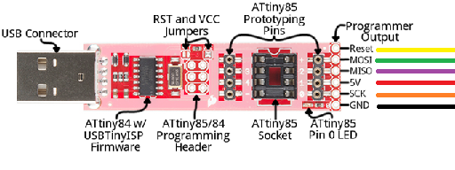
The Tiny AVR Programmer has an existing pinout for the SPI interface signals but a 6-pin header must be soldered to the outputs in order to extend the signals to the breadboard.
After soldering, follow the Sparkfun hookup guide to install the required USBtinyISP driver (before plugging in the Programmer to a USB port). To complete Programmer setup, connect jumper wires to the newly soldered header. The signal names and recommended wire colors are shown in the diagram above.
Notice that the Sparkfun Programmer has an onboard socket for ATtiny85 programming. The socket together with the 4-pin access headers on either side allow download and prototyping for the tiny85/45/25. However, this approach is restricted to the tinyx5 devices. On the other hand, the SPI interface allows programming and in-circuit test/debug of most of the ATmega, AT90, and ATtiny microcontrollers. An excellent discussion of application of the SPI interface for programming of AVR microcontrollers can be found here. While this is an application note for use of the Equinox programmer, the conclusions apply equally well to the Tiny AVR Programmer.
Step 4: BreadBoard Layout for ATtiny84

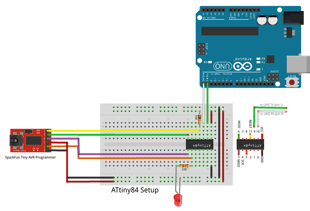
Now populate the breadboard with the hardware components as shown in the fritzing diagram above for the ATtiny84. It’s probably best to orient the components and connections as closely as possible to those in the diagram in order to reduce the risk of connecting an SPI or Serial signal to the wrong pin. (Note that the pin numbers listed in the diagram are the Arduino Pin numbers, not the device physical pin numbers.)
- All 6 Tiny AVR SPI signal lead wires are connected
- VCC (red) to the breadboard power rail
- MOSI (green) to the tiny84 pin 6 (MOSI)
- MISO (purple) to the tiny84 pin 5 (MISO)
- RESET (yellow) to the tiny84 pin 11 (RESET)
- SCK (orange) to the tiny84 pin 4 (SCK)
- GND (black) to the breadboard ground rail
- The LED is connected via a 300 ohm resistor to Pin 4 (SCK)
- A 10K pull-up resistor connects power to RESET
- assures that RESET doesn’t get unintentionally activated after upload.
- Three of the four signals on the USB to Serial cable are connected:
- Ground (black) to breadboard ground rail
- Transmit(green) to receive pin assigned to SoftwareSerial (pin9)
- Receive (white) to transmit pin assigned to SoftwareSerial (pin 10)
- Power (red) should not be connected since power is being supplied by the Programmer
Step 5: Program Explanation
The serial output example program (listed below) is based on the Arduino Blink example program with additions for SoftwareSerial support. The following table explains the additional serial support statements:
| Statement | Purpose |
|---|---|
| #include | Gain access to the Software Serial class functionality |
| #if defined...#else | This section assigns device specific pin number functionality |
| #error | Defining pins only for tiny84/85 so stop compile if not one of these |
| SoftwareSerial mySerial(rxPin,txPin); | Instantiate a SoftwareSerial variable to be used for serial output |
| mySerial.begin(9600); | Initialize/start SoftwareSerial communication at 9600 baud |
| mySerial.println(text); | Send text to the serial output window for display
|
//************************************************************************
//  PART 1: Serial output setup and example output:
//  .  Modifies the example Blink code to illustrate serial output
//  .  Common code for ATtiny85 and ATtiny84
//************************************************************************
#include <SoftwareSerial.h>		// Arduino SoftwareSerial class

// While the processing code is common, the pins used are device specific
#if defined(__AVR_ATtiny84__) || defined(__AVR_ATtiny84A__)
	#define ledPin  4               // Toggle to turn connected Led on/off
	#define rxPin   9               // Pin used for Serial receive
	#define txPin   10              // Pin used for Serial transmit
#elif defined(__AVR_ATtiny85__)
	#define ledPin  1
	#define rxPin   4
	#define txPin   3
#else
	#error Only ATiny84 and ATtiny85 are Supported by this Project
#endif

// Create instance of the Software Serial class specifying which device
// pins are to be used for receive and transmit
SoftwareSerial mySerial(rxPin, txPin);

//------------------------------------------------------------------------
// Initialize processing resources
//------------------------------------------------------------------------
void setup()
{
  mySerial.begin(9600);       // Start serial processing
  delay(2000);                // Give Serial class time to complete initialization.
                              // otherwise, 1st output likely missing or garbled

  pinMode(ledPin, OUTPUT);    // Configure led pin for OUTPUT

  mySerial.println("SETUP Complete - SoftwareSerial Example");
}

//------------------------------------------------------------------------
// Toggle the led; document HIGH/LOW with serial output messages
//------------------------------------------------------------------------
void loop()
{
  // Turn led on; display "it's on" message
  digitalWrite(ledPin, HIGH);
  mySerial.println("LED ON");
  delay(2000);

  // Turn led off; display "it's off" message
  digitalWrite(ledPin, LOW);
  mySerial.println(" LED OFF");
  delay(2000);
}
Step 6: Run the Program
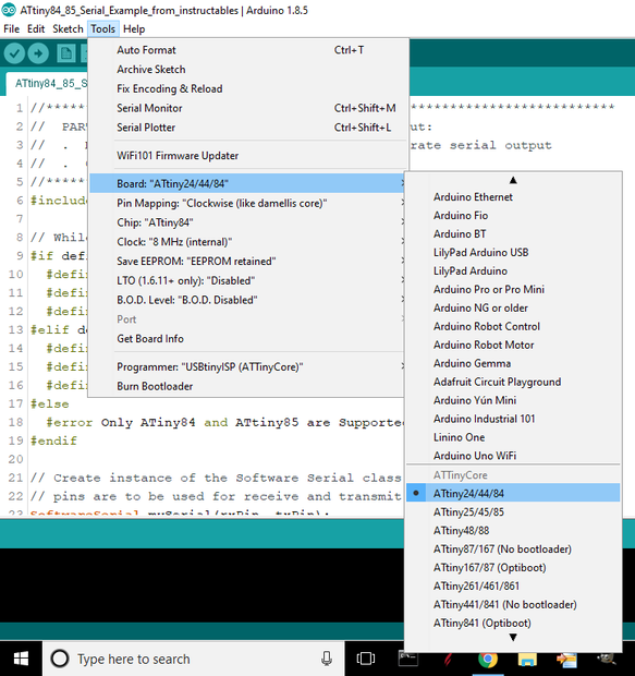
| Set Board to ATtiny84 | Set Programmer to USBtinyIsp (ATTinyCore) |
|---|---|
 |  |

The environment is now complete. Follow the steps below to run the program:
- Copy the example program into the Arduino IDE
- Configure the IDE (as shown above) for the ATtiny84 and compile
- Board: "ATtiny24/44/84"
- Pin Mapping: "Clockwise (like damellis core)"
- this is the default but inadvertently changing it has CATASTROPHIC consequences
- Chip: "ATtiny84"
- Programmer: "USBtinyISP (ATTinyCore)"
- Plug in the Tiny AVR Programmer to a PC USB port
- Plug in the Adafruit USB to TTL Serial cable into a second USB port
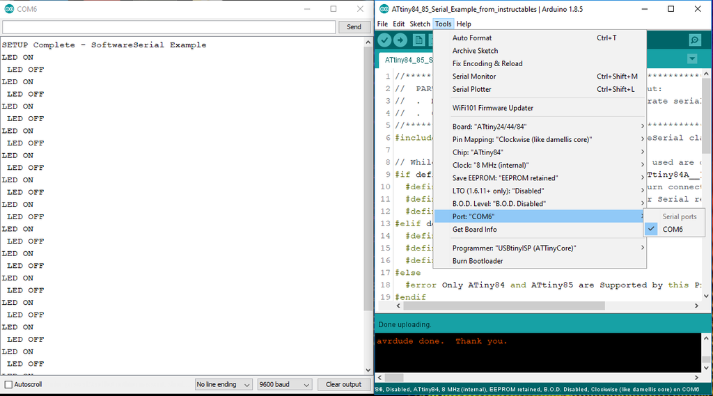
- A COM port is created and will be added to the Arduino IDE Port list
- Select the port created in step 4 (COM6 on my system) and launch the COM window
- Click the upload program (right arrow) button at the top of the Arduino IDE
- The program will be loaded to the microcontroller and start to run
- The led blinks on and off at 2 second intervals
- The following serial output messages are written to the COM window
- SETUP Complete - SoftwareSerial Example
- LED ON
- LED OFF
- … led on, led off message sequence repeats in unison with the led blink
Step 7: Setup and Run Program for ATtiny85

All the steps in preceding sections for the ATtiny84 also apply to the ATtiny85. Since the software environment is already setup at this point, it is only necessary to configure the hardware as shown in the ATtiny85 Fritzing diagram above, change the processor to ATtiny85 in the Arduino IDE, compile and run the program as described in Step 4.
Step 8: Miscellaneous

- The Arduino UNO can be used for Serial output instead of the Serial cable:
- Connect the UNO’s dedicated receive (pin 0) and transmit (pin 1) pins to the microcontrollers receive and transmit pins. Note that the connections are receive-receive, transmit-transmit instead of receive-transmit, transmit-receive as they are when using the Serial cable.
- Run the Arduino examples Minimum program (empty setup; empty loop) on the UNO
- Launch the (already available) COM window from the IDE (COM3 on my laptop)
- Upload and run the Serial output program on the tiny84/tiny85
- The serial output messages will appear in the Arduino COM window

- The Serial cable can support stand-alone run by disconnecting the SPI interface from the breadboard and connecting the power lead from the Serial cable to the breadboard power rail. It will be necessary to use a terminal emulator utility like PuTTY to connect to the Serial cable’s associated COM window instead of the Arduino IDE. PuTTY configuration is outlined below. A full explanation can be found here.
- Download PuTTY and double-click on the associated Icon to launch the PuTTY Configuration window.
- Configure PuTTY for Serial output by clicking on the Serial Connection type button
- Plugging in the USB Serial cable creates a COM port which is listed under the windows Device ManageràPorts (COM & LPT)
- Enter the name of the COM port in the PuTTY->Serial Line configuration window
- The default baud rate is 9600 which is correct for this application
- Click on the Open button at bottom of PuTTY Configuration window to launch the serial output window
- The serial output messages will be displayed in the COM window

Participated in the
Microcontroller Contest


