

Introduction: An Auto-winder for a Weight-driven Clock


I have a clock that's around 150 years old. It's what's known as a "Black Forest Clock" or a "Shield Clock" and is driven by a weight. I can never remember to wind it so I thought I'd build an electric auto-winder. After several complicated prototypes, I finally settled on a simple design that I've called the "P2-Winder".
I wanted something that was simple to build, self contained, reasonably inconspicuous and didn't require a complex fitting. As far as I know, my design based on shifting the centre of gravity is completely new. (But my experience is that whenever you think you've invented something, you find someone else got there before you!)
This Instructable tells you what I did. You can copy it exactly and ignore my discussions and explanations. Or learn from my mistakes and design your own using whatever components you have to hand.
Auto-winders are often fitted when restoring church clocks. There are very few designs published for auto-winders. Church clock winders sometimes just replace the person who turned the handle with an electric motor but that design means the tension on the chain is relieved for several seconds: the clock can stop or lose time. A better design is the Huygens Endless Rope which is automated to give an electric version of the Robin remontoire.
Some people make winders based on a continuous loop remontoire but they're often rather clunky and suitable only for long-case clocks where they can be hidden. In all the designs, they use a microswitch or similar to decide when to turn the motor on and most are mains-powered.
Richard Thomas has designed a chain-climbing winder for a long-case clock. It replaces the weight with the chain passing through the centre. The motor is switched on when the weight reaches the bottom of the case and off when the weight reaches the top. He claims three or four AAA cells last for 6 months. His is a complex design with lots of moving parts. I started with something similar but eventually simplified it down to what you see now.
Supplies
The P2-winder is made with hand tools. We think of "clock-making" as high-precision work by a skilled craftsman but this project really isn't.
The materials all came from my scrap box. I used the following:
- a JS-30 motor, 5RPM or 7RPM, 3V or 6V
- sheet steel or brass, a few square inches, 0.5mm and 1.7mm
- a reed switch
- a magnet 1.6x5.5mm
- a brass rod 25x6mm
- battery holder for 2 or 3 AA cells
- wooden sheet, 3mm and 2mm
No doubt you will use whatever you have in your scrap-box and adjust the design accordingly.
Step 1: The Chain Wheel


Start by removing the weight and making the chain into a loop.
The P2-Winder sits at the bottom the the chain loop. It contains an electric motor and the whole contraption works like a monkey climbing up a rope.
The chain wraps around a toothed chain-wheel. A motor and gearbox turn the wheel.
The original clock weight hangs below the "taut" side of the looped chain. As the clock runs, the taut chain lengthens and the loose chain shortens. That action rotates the winder counterclockwise until a tilt-switch switches on; the motor turns the chain-wheel and the winder rotates clockwise. The total rotation of the winder is about 20 degrees.
The chain wheel is made as a sandwich of different layers bolted together. It does not have to be very accurately made - hand tools are good enough. I used steel of different thicknesses plus a little thin card as padding. The innermost layer has the teeth. The teeth must be long enough to engage the chain but short enough that they easily enter the holes in the chain. Look at the main chain-wheel of your clock and see how they've done it. The regions between the teeth can be roughly made as the chain does not touch them. The layers on either side form "shoulders" which support the chain; they must be far enough apart that the "vertical" links can fit between them. The outermost layers guide the chain onto the teeth; they must be far enough apart that the "horizontal" links can fit between them.
I sawed and filed the toothed-wheel by hand. The circular disks were sawed out then cleaned up by filing them while spinning them in an electric drill. They're made of steel but would look a lot nicer if they were brass. No doubt a "real" clockmaker would be appalled at what I've made but it is 100% reliable.
I've drawn the dimensions of my chain wheel. Measure your chain and scale everything appropriately. My clock has the weight on the left; if yours is on the right, you'll have to reverse everything.
Attachments

Step 2: The Motor


In theory, any low-power motor-plus-gearbox can be used. The essential requirements are that it should have enough torque and that it should not be possible to back-drive it. I started with a commercial gear-motor which appeared good but, under some conditions, would back-drive. Then I chose a strong motor from a toy which did not back-drive. It worked well for about a month before the brushes failed. Toy motors are not good quality. You need a motor that will run for years.
The chain wheel is 15mm radius and the weight is 550g; that's a torque of 0.825kg.cm. So you'll need a motor with at least that torque.
Eventually I settled on a JS-30 motor. They're widely available, cheap and reasonable quality. Search eBay or your favourite supplier for "JS-30 motor" or "gear motor". They come with a variety of gearboxes and coil-windings. I happened to already have a "6V" "7 RPM" version. You need a "5 RPM" or "7 RPM" gearbox as higher rotation speeds can be back-driven.
The motor takes 45mA under the winder's load and allegedly has a stall torque of 2.5kg.cm.
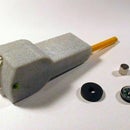
Step 3: The Tilt Switch


The motor is controlled by a home-made tilt-switch.
At first I used a mercury tilt-switch; it's what I had to hand. But I found it was unreliable - it wouldn't always make good contact. It worked well with the original toy motor which took a large current but didn't always work with the low-current JS-30 motor. And, of course, nowadays, one should be politically correct and use a non-mercury switch. Then I tried a modern tilt-switch containing a gold-plated ball: it worked for a fortnight then failed once. That's one in 2000 operations. A gentle tap fixed it but that's not good enough.
I'm now using reed switch and it's been completely reliable. It's meant to be good for 1,000,000 operations (i.e. approx 4 years) with 90% reliability for 100,000,000 operations.
A magnet is suspended above the reed switch with the poles vertical. As it swings from side to side, it operates the reed switch. When the magnet is centred on the reed switch, the contacts of the reed switch are magnetised in opposite directions so repel each other. If the magnet is to one side of the reed switch, the contacts are magnetised the same way so attract each other and turn on.
The body of the reed switch is 20x2mm. Just search eBay or your favourite supplier for "reed switch".
I made the suspension from 0.7mm copper wire (from mains wiring). It's easy to work with and solders well. Brass or aluminium or plastic would work too, just so long as it's non-magnetic. I used a 1.6mmx5.5mm neodymium magnet glued onto the end of a brass rod. You don't want a very strong magnet or it will be distracted by the motor. (I found a 2mmx5mm magnet was too strong and a 1mmx3mm magnet was too weak. It will depend on your setup.) A ferrite magnet would work too but be careful of fridge-magnets: they have weird field patterns. There are end-stops to prevent the magnet from swinging too far.
The attachment of the tilt-switch to the winder should be adjustable so you can set its operating point. The body of the motor is about 25mm diameter and is a useful attachment point. I started by using a spring clip ("Terry" clip, conduit clip or capacitor clip) but then changed to Blu-Tack. Once I'd worked out the correct angle, I screwed the switch in.
Step 4: The Mechanics


The winder works because the centre of gravity (CoG) of the box-plus-weight moves so it's critical that you get it right. The CoG should be to the right of where the taut chain meets the wheel; if it is to the left, the box will freely rotate anti-clockwise. The CoG should be below the centre of the chain-wheel otherwise the box will fall towards or away from you. That must remain true as the box rotates. The shaded red region is suitable.
Overall, the box adds 25% to the clock-weight. That weight is balanced between the two sides of the chain so it shouldn't affect the torque on the clock's chain-gear. However the extra weight will affect the friction at that chain-gear's bearing. So try to keep the weight of the box down.
The box weighs 140g; the weight weighs 550g. The CoG of the box should be somewhere near the top-centre. The CoG of the weight is applied at its attachment point at the bottom-left. The weight of the box is 20% of the total so the combined CoG will be 20% of the way from the weight attachment point to the box CoG.
I kept the CoG of the box high by fixing the AA cells above the motor.
The idea is that, as the winder rotates, the CoG moves up and down but doesn't move much to the left and right. That means that the tension on the taut chain keeps roughly the same values. The loose chain mustn't hang too loosely and get tangled. The tension in the chain will vary but it's not too critical - the chain weighs 50g and the weight is 550g so, in the original arrangement of the clock, the torque at the clock's chain wheel varied by around 20% as it wound down.
The overall construction is very simple; I made it from scrap wood. The "front panel" is a piece of 3mm ply onto which everything is screwed or glued. The weight hangs on a peg of 5mm dowel. I filed a groove in the peg to stop the weight moving. The peg is a tight fit in its hole so I could slide it in and out to get the weight to hang right - then it was glued in place.
The remainder of the box is simply for show. The sides are 2mm wooden sheet. The back is left open to provide access to the battery box. The wood is stained and polished to look antique.
Attachments
Step 5: Power

Let's do some maths. If you don't like that sort of thing then just skip this part.
The weight is 550g and drops around 1.7m in a day. That's 9.2 Joules per day or 3.3kJ/year and is about 100uW. A cheap AA cell in a modern quartz clock holds around 6kJ and lasts about a year. So a 150 year old clock is more efficient than modern electronics. Nice!
The gear-wheel has 8 teeth for the chain, i.e. 16 links. The chain links are 12.5mm per two links. So that's 100mm of chain per revolution. That's 17 revolutions per day. At 7 RPM that's 2.4 minutes. The motor takes around 45mA. Which gives 1.8 mAh per day: 75uA or 340uW. So the three 1000mAh cells should last 1.5 years. That calculation doesn't account for the starting current to be bigger so the real average current will be higher and AA cells self-discharge. It implies we can use AA cells.
I used 3 AA cells because I have a "6V" motor. (Two AA cells weren't enough for my "6V" motor. You could buy a "3V" motor and use two AA cells to keep the weight down but the two AA cells will need replacing more often.)
Step 6: Future Improvements

The tilt switch could be replaced with an accelerometer. It would be more reliable.
I'd use a PIC micro (e.g. the 16F87 or 12F629) as the driver. (Arduinos can't be made to sleep at a low enough current. An ATTiny can sleep well.)
It would be better to use a brushless motor. The brushes are going to be the main failure point (the reed switch should be very reliable). I haven't tested the circuit above, it's just a rough sketch. A 24BYJ48A stepper motor looks promising (search eBay). It's 5V 40mA and the 80:1 reduction ratio should give sufficient torque and probably can't be back-driven.
"Everyone says" that stepper motors are less efficient than brushed motors but no-one says how much less. I've now done some experiments winding a weight up onto a drum. With the motor described above, calculating electrical_energy_in / mechanical_work_done gives 20% efficiency. With the similarly sized and similarly geared stepper it was 2% efficient. So if you want it battery-powered, don't use a stepper.
Maybe it would all run off a single 3V Lithium cell.
The next stage would be to add an electromagnet to synchronise the pendulum so the clock keeps perfect time.

Participated in the
Clocks Contest

![Tim's Mechanical Spider Leg [LU9685-20CU]](https://content.instructables.com/FFB/5R4I/LVKZ6G6R/FFB5R4ILVKZ6G6R.png?auto=webp&crop=1.2%3A1&frame=1&width=306)


