

Introduction: Flux Gate Magnetometer Experiments


This Instructable describes my progress in building a flux gate magnetometer.
Flux gate magnetometers are very much more sensitive than Hall Effect magnetometers. The theory behind them is straightforward and is described in Step 1.
It's not easy finding a core that will work for a fluxgate. NASA makes fluxgates using cores from a single melt of 6-81 Permalloy that was created for the U.S. Naval Surface Weapons Center in 1969. They are now running out of the alloy and are a bit worried. Step 2 describes what is required of the magnetic core and how to choose one made of materials available to a hobbyist. Subsequent steps describe my experiments with different cores.
The magnetometers I describe use an Arduino (Uno or Nano), a L293 or L293D H-bridge driver and an LM358 op-amp. In my circuit diagrams, I power the drive coil from the 5V supply. If you build a battery powered version (e.g. 4 AA cells) then you should power the drive coil directly from the battery (the L293D can do that).
It would help while building this device if you have an oscilloscope but it's not essential - the Arduino (and a PC) can act as a simple oscilloscope.
In this Instructable, I'll always measure flux density in microTesla (uT). Some magnetometers are specified in milliGauss (mG):
- 1mG = 0.1uT
The Earth's magnetic field where I live is 50uT and inclined at 70deg into the ground. My best flux gate magnetometer had a noise-floor of 0.5uT.
When compiling my Arduino code, turn off warnings. My code produces a lot of warnings which I find excessive and unhelpful. In the Arduino IDE (ver 1.8 or higher) select the File|Preferences menu item to open the Preferences dialog. Set Compiler Warnings to "None". Close the dialog.
This is an "experimental" project. If you copy exactly what I did then you should end up with a reasonably sensitive magnetometer but what I hope you'll do is use your own experiments to make it better.
Step 1: How It Works


There are lots of descriptions on web of how a fluxgate magnetometer works. Here's a brief summary.
You start with a toroidal ring of a magnetic material, for instance ferrite, often called a "core". It doesn't have to be a round ring. Many flux gate magnetometers use two straight rods.
A drive coil magnetises the core alternately cw and ccw. It magnetises it so it's saturated in each direction. "Saturated" means all the magnetic domains in the core are pointing the same way
A sensor coil is wound around the whole core and driver coil. As the core saturates, small positive and negative pulses are generated in the sensor coil. Their shape and timing depends on the external magnetic field.
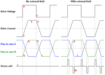
The timing diagrams above show the process in detail:
The square wave drive voltage produced by the Arduino is positive (A). The magnetic flux inside the ring starts to rise (B) and the current through the drive coil starts to rise (C). The slope of the rise in current (in amps per second) is equal to
- dI/dT = V / L
So the bigger the inductance, the slower the current rises. The current is being used to build the magnetisation inside the core. The flux density is proportional to the current.
Eventually, the core saturates (D). The magnetic flux in the core can't get any stronger. The drive current is limited by the resistance of the coil (E).
The square-wave drive voltage changes to negative (F). The current drops rapidly (G). The core starts to de-saturate (H). And the whole sequence repeats in the other direction (I).
You should think of the core having two halves – the upper half (“core A”) and the lower half (“core B”). The two halves are magnetised in opposite directions: left to right or right to left.
The voltage in the sense coil (J) is proportional to the rate of change of the flux. As far as the sense coil is concerned, the flux in the upper half of the core (“core A”) is to the left whereas the flux in the lower half of the core (“core B”) is to the right. They cancel out and no voltage is generated in the sense coil.
In the presence of an external field, the upper half of the core (K) saturates before the lower half does (L). When that happens, the two changing fluxes no longer cancel and a signal is produced in the sense coil (M). In this example, there is a short positive pulse in the sense coil just before the square (driving) wave goes negative and a short negative pulse in the sense coil just after. If the external field were in the other direction, the order of the pulses would be reversed.
In practice, the waveforms are more complicated than I’ve described. The current in the coil exponentially approaches a maximum rather than rises linearly (C). The sense coil picks up spikes from the drive coil rather than just from the core (J,M). When the core is saturated, the current in the drive coil can rises faster because it is no longer having to use its energy to make more magnetic field (E).
So the circuitry must be able to produce a square wave for the drive coil and be able to measure the sense coil pulses.
Step 2: What Is Saturation?


You want the core to saturate - that's how a fluxgate magnetometer works. So what is "saturation"?
In an unmagnetised core, the magnetic domains all point in random directions. When the domains point same way the core is "saturated"
When an external field is applied to the core (e.g. by a coil), the domains start to point in same way. That makes the field inside the core get even stronger. It’s as though the core has “amplified” the field.
As each domain re-orientates, there is a sudden change in the flux which is picked up as a spike in the coil. This is known as Barkhausen noise and may limit the resolution of magnetometer.
The relationship between the external field (H) and the internal field (B) is called "permeability". The bigger the permeability, the more the internal field grows for the same external field
From the BH curve, you can see that when the permeability is high (the slope is steep), the cores will go into saturation faster. Conversely, when the permeability is low, the cores saturate at a much higher external flux density.
As the magnetisation of the core increases, it generates a voltage in the coil which opposes the field the coil is trying to produce. The voltage is proportional to the rate of change of the magnetic field. That opposition is what gives rise to the "inductance" of the coil
When the core saturates, its magnetisation no longer changes so the induced voltage is less and the inductance falls. You can see that in the graphs (above) of a typical MuRata inductor. The change in inductance during saturation was the basis of magnetic amplifiers of the early 20th century.
The strength of the external field (H) and hence the internal field (B) depends on the current through the coil and the number of turns.
The inductance depends the number of turns squared.
Most users don't want to saturate the core so the manufacturer specifies the maximum current through the coil before the core saturates.
The magic number for a core is the inductance factor (AL). The inductance factor allows you to calculate how many turns of wire you need to get a particular inductance:
- L = AL*N*N
where
- L: inductance in Henries
- AL: inductance factor
- N: number of turns
If you're buying a core, it's worth buying one from a manufacturer that tells you the inductance factor (many don't tell you!).
There are formulae and websites that will calculate AL from the dimensions of the core. They may use different formulae and they all ask you for the relative permeability of the ferrite. The problem is that you may not know the permeability. Relative permeability can range from 10-20 to as high as 10,000!
Saturation is caused by flux density B in the core reaching the maximum the core can handle. The value of Bmax is
- Bmax = ( AL * N * I ) / area
where
- Bmax = flux density in Teslas
- L = Inductance in Henries
- I = Current in amps
- area = core cross sectional area in square metres
- N = number of turns of the coil
For ferrite, assume saturation occurs when Bmax=0.3 or 0.4 Teslas. I'm going to discuss ferrite here but many cores are made from MPP (molypermalloy powder) which saturates at 0.75 teslas.
There is no definition of when the core is saturated but at saturation, the inductor has lost maybe a third of its original inductance. Ferrite tends to have a sharp "knee" - it saturates suddenly. Soft iron saturates gradually so doesn't produce the sharp pulses in the sense coil.
How long will it take for the core to saturate? If you switch on the current through a coil, the back-emf generated by the coil starts high and drops exponentially. The time-constant of that exponential drop is a very rough indication of how long it will take to saturate the core.
- time constant = L/R
We know L and we can measure the resistance of the coil. For instance, one of the coils I wound had an inductance of 200uH and a resistance of 1.4ohm. Of course, we have to worry about the "resistance" of the driver circuit - which is probably non-linear - but it gives us a rough idea.
- time constant = 200 / 1.4 = 143 uS.
Let's increase that to 200uS to be sure the core has saturated. The core saturates in one direction then the other so that's 400uS which implies a square wave of 2500Hz. In general, a flux gate magnetometer is driven at a few kHz.
Step 3: The Circuit

The circuit diagram I used for my experiments is shown above. An Arduino (Nano or Uno) produces a square wave which is fed to an L293D H-bridge driver. The L293D can supply 600mA but soon overheats if asked to do so continuously without a heatsink. The Arduino sketch produces pulses that energise the coil for less than 10% of the time. A USB supply might be limited to 500mA. The average current of the circuit is around 100mA.
The L293D can have a different supply for the "logic" (5V) and the "power" (4.5V to 36V). In the circuit above I've labelled the "power" input as "5VA". You can connect the 5VA line to the 5V line but put a 100uF capacitor on them. In theory, connecting them together should produce more noise; in practice, it didn't.
The op-amp amplifies the signal from the sensor coil and passes it to an ADC in the Nano. You can change the gain of the op-amp by changing R1 and R2. C2 smooths the noise of the sensor signal. I’ve used 100nF but you could try, say 10nF or 1nF.
The mid-point of the op-amp is defined by R4, R5, R6. It should be set to approximately 1.7V (because the LM358 output swings between 0.02V to 3.5V).
The Fluxgate1.ino sketch can be downloaded below (when compiling, turn off warnings).
The sketch produces a "positive" pulse for 2mS. Then it produces a "negative" pulse for 2mS and measures the response from the op-amp. Then it produces a "positive" pulse for 2mS and measures the response from the op-amp. The output due to the first "positive" pulse is not measured - that pulse sets the core into a known state as though the pulse train was continuous.
The Nano transmits the measurements to a PC with the following format:
- 0xAA
- 0xBB
- 0xCC
- 2 bytes: elapsed time for whole buffer
- 500 bytes: measurements for "negative" pulse
- 500 bytes: measurements for "positive" pulse
The using Magnetometer.exe windows program graphs that output. You can use an oscilloscope to view the output if you prefer.
The ADC is set up in fast 8-bit mode. That's not ideal for measuring the output of the magnetometer but it shows the shape of the waveform.
If an external magnetic field is applied to the magnetometer then after each change in direction of the pulse, the output of the sense coil first goes positive then, after a delay, goes negative. If an external magnetic field is applied in the other direction then the output goes negative then positive.
The delay is the time it takes for the core to saturate.
To take a reading, you would measure the output a few times before saturation then a few times after saturation. The using Magnetometer.exe program shows the times at which you might take readings (drag them with a mouse). Subtract the positive ones (green) from the negative ones (blue) to get a reading. You can see typical screenshots below (e.g. Step 6).
You can smooth the sense coil output by putting a capacitor across it to make a tank circuit. The resonant frequency of the tank circuit should be twice the frequency of the drive voltage – so 500Hz in this case.
- freq = 1/(2*pi*sqrt(L*C))
My sense coil was 4.3mH which gives C equal to 23.5uF. So I put two 47uF capacitors in series (anode-to-anode) to make a bipolar capacitor. It didn’t make much difference to the noise level or sensitivity.
Attachments

Step 4: Does a Ferrite Toroid Work?


You want the core to saturate - that's how a fluxgate magnetometer works. This Step explains the factors involved in choosing a core.
The toroidal cores you buy on eBay or wherever are being sold to make switched-mode power supplies or for transient suppression and the users don't want the core to saturate. You could make a magnetometer using such a core but you would need a huge current or a huge number of turns to saturate it.
How big should the core be? A bigger core is easier to wind. A smaller core is easier to saturate.
It can be cheaper to buy an inductor on eBay than a core. The current they quote in the advert is (usually? always?) the saturation current - it's best to look at the manufacturer's document to be sure. Let's assume you buy:
- 12mm outside diameter (OD)
- 8mm inside diameter (ID)
- 4mm thickness (h)
- 50 Turns (N)
That probably means a saturation current of 2A.
2A will flatten our battery very quickly. Let's say we'd prefer 50mA; that would require 40 times as many turns, i.e. 2000 turns. You wouldn't want to wind that by hand because for every turn you have to poke the wire through the hole in the core.
Let's say you already have a ferrite core you've salvaged from some equipment or bought on eBay. I salvaged a core which had 44 turns and 90uH inductance which gives
- AL = L/(N*N) = 0.00009/(44*44) = 46nH
Be careful of the units of AL in the manufacturer's catalog. I've calculated it in nanoHenries.
My core is
- 12mm outside diameter (OD)
- 8mm inside diameter (ID)
- 4mm thickness (h)
So if you've got a random core, wrap a few turns round it and measure its inductance. Perhaps your multimeter can measure inductance. If not, you should buy an LCR-T4 meter on eBay - it's a tremendously useful device. If you have neither, there are many web pages explaining how to use an oscilloscope or an Arduino to measure inductance.
Or you could go to eBay and buy, e.g., a 100uH inductor and count the turns. But don't. Ferrite (or MPP) cores are not that good for making a fluxgate magnetometer.
The core has to saturate. That's how a fluxgate magnetometer works. What you're interested in is:
- how much current do I need to pass through the coil to get saturation?
- how many turns should the coil have?
- what frequency should I use?
Remember, the value of Bmax is
- Bmax = ( AL * N * I ) / area = 0.4
For the core I was testing
- AL = 46nH
- 12mm outside diameter (OD)
- 8mm inside diameter (ID)
- 4mm thickness (h)
- 50 Turns (N)
- Bmax = 0.4
- So
- 0.4 = ( 46e-9 * 50 * I ) / (0.004 * 0.004)
- I = 2.6A
which is close to my estimate of 2A.
The calculations are extremely complex but, very approximately, if the core is half the size (i.e. you halve every dimension) then you need half the current or half the turns to saturate it. So a small core will saturate more easily.
You could get a small toroid core. I have some that are 6mm outside diameter; I think they're from magnetic logic in the 1960s. I wound 100 turns of fine wire on it (to give 100uH). With a 50mA average current, it would saturate and act as a magnetometer but it wasn't very sensitive. I had trouble measuring the Earth's magnetic field (50uT). Because it was wound by hand, by poking the wire through the hole, the windings were uneven. There were more turns on one side that the other which meant the one side always saturated first so it didn't give a "zero" reading. It would be possible to make a magnetometer with such a small core but very difficult.
Unfortunately noise goes up and sensitivity goes down as the core gets smaller. I think the higher noise is due to it having fewer domains and hence more Barkhausen noise. I suppose a bigger core captures more of the external field you're trying to measure.
So a big ferrite core is too difficult to saturate and a small ferrite core is noisier and not so sensitive. How about a commercial inductor that's not a ring?
Step 5: Bobbin Inductor

Small "bobbin" style inductors are cheap and are already wound. Can we use two of then side-by-side?
I have a range of small inductors from 1mH to 100mH. The data sheet tells us the inductance, the current when the core first begins to saturate and the resistance. From that we can calculate the voltage needed to saturate the core.
L     I     R    V
2.2mH 0.50  2.0  1.000
3.3mH 0.42  2.5  1.050
4.7mH 0.35  3.5  1.225
6.8mH 0.29  5.7  1.653
10mH  0.23  7.3  1.679
15mH  0.19  12   2.280
22mH  0.15  22   3.300
33mH  0.13  26   3.380
47mH  0.11  36   3.960
68mH  0.09  57   5.130
100mH 0.07  90   6.300
I wanted to put the two inductors in series (so the current through them is equal) and I wanted to be sure the core is fully saturated so I chose two 4.7mH inductors.
MuRata and some other manufacturers (but not all) make one lead longer than the other. That tells you the direction in which the coil is wound. If your coil doesn't tell you, put a few mA through it and watch how it affects a compass.
Tape the two cores together and wrap, for instance, a hundred turns around it as a sense coil. Connect the coils in series to the H-bridge driver and send a 1kHz square wave through it. You can use the circuit in the previous Step. Make sure the coils are connected so the fields they produce oppose each other.
After I'd wound the sense coil, I found it picked up slightly more field from one coil than the other so I added a resistor in parallel with one coil to balance them. For me that was 180ohm.
The result? It didn't work.
The sense coil hardly measured any external field. It would sense something if I brought a strong neodymium magnet close to the cores but that was probably because the external field from the neodymium magnet was itself saturating one of the cores.
Why didn't it work? Maybe the MuRata inductor is designed not to leak much field. Inductors are often placed near to each other and you don't want the field from one to affect another. If the inductor doesn't leak much field to the outside then it won’t absorb much field from the outside.
So where can we get a core from?
How about the core from a transformer?
Step 6: A Transformer Core


If you take apart scrap electronics from the 1960s you'll almost certainly find a small transformer. In the days before there were both PNP and NPN transistors, it was how you drove a loudspeaker (a "Class-B transformer-coupled amplifier"). Every transistor radio had a transformer. So I took a scrap transformer apart and extracted the core.
The core is made from laminated steel to minimise eddy current loss. The steel is chosen to have high permeability and high electrical resistivity.
I cut an E-shaped lamination in half to make a U-shape - each arm is 2.1x0.36mm. I wrapped 100 turns of 0.25mm diameter "transformer wire" around each arm. Make sure you have the centre-tap. It can come in handy. To make it easier to apply the turns, I fed the wire through a fine propelling pencil. I glued a bar across the open end of the "U" to make it into a ring. I don't know if the ring shape is necessary - it just felt like the right thing to do.
The result had an inductance of 200uH which gives an inductance factor of
- AL = L/(N*N) = 200e-6/(200*200) = 5nH
Transformer cores are usually made from "electrical steel" which saturates at a flux density (Bmax) of 1Tesla to 2Tesla (remember, ferrite saturates at 0.4 Tesla).
- Bmax = AL * N * I / area
if Bmax = 1 then I = 0.75 Amps which is inconveniently high.
Did it work? Yes, surprisingly. The current through the coil was an average of 130mA which, according to my calculations, is way too small to saturate the core. (Maybe I made a mistake in my maths. An online calculator suggests AL should be nearer 100 which implies saturation at 40mA.)
But once again, it wasn't very sensitive. It could just about detect the earth's magnetic field but was probably has a resolution of 10uT. Once again, I think it was too small.
So I made a bigger one.
Old "wall wart" ("swinging brick") power supplies also contain a transformer. I wouldn't want to pay more than £0.50 in a car boot sale or £1 in a charity shop. You can tell which ones have a transformer because they're small and heavy. If it's light-weight it will be a switched mode power supply: much better quality but not what we want here.
A transformer core is made of "electrical steel". If you can't find a transformer, I suppose you could try using mild steel but it's not as good
- mild steel: permeability = 2000, Bmax = 2.4T
- electrical steel: permeability = 4000, Bmax = 1.7T
So if you use mild steel, you will need an external field that is 2.8 times bigger to saturate it.
Did it work? Yes!
I could easily measure the Earth's magnetic field.
The Fluxgate2.ino sketch can be downloaded below (when compiling, turn off warnings).
The sketch makes 4 readings of the sensor output as described in Step NNN. It uses the full 10-bits of the ADC. The timings of those readings will depend on your coil so you may have to adjust them. The times since the change of the driver (in uS) are in the SampleTime[] array. The first half of the readings are the positive ones (green) and the second half are the negative ones (blue). The sketch uses the analogRead() function which takes over 100uS for a single reading so if you adjust the timings of the readings you won't be able to get them closer together than that.
With 300 turns for each of the driver coils and 200 turns for the sense coil the op-amp needed a gain of 3. By increasing the sense coil to 500 turns (of 0.12mm wire) I could do without the op-amp and connect the sense coil directly to the ADC.
The sketch smooths the readings slightly then sends them to the PC as ASCII. You can graph them using the Serial Plotter tool in the Arduino IDE.
How can you tell how sensitive it is? Search the web to find the strength of the Earth's magnetic field where you live and its direction. For me it's 50uT, inclined at 70deg into the ground. Turn your magnetometer to give a maximum positive reading then turn it to give a maximum negative reading. Subtract one from the other - for me that's 100uT. For me, the values sent to the PC then ranged from +70 to +120 so one ADC "count" is about 0.5uT. The noise floor was around 0.5uT.
The graph above shows me turning the sensor round to measure the Earth’s magnetic field “forwards” (50uT) then “sideways” (0uT).
Attachments
Step 7: Saturated Core Magnetometer


I suspected that the noise in the fluxgate magnetometer to be mostly due to the op-amp and the ADC. It might be due to all the equipment I have nearby but I don’t think so: mu-Metal or electrical shielding made no difference. It also might be Barkhausen noise. Is it possible to make a magnetometer which does not require an ADC?
Imagine a core that is alternately magnetised to saturation in one direction then in the opposite direction. When the driving voltages switches direction, the current through the coil, and hence the degree of magnetisation, will start low and gradually increase. The degree of magnetisation will stop rising when the core saturates. If there is an external magnetic field then the saturation will happen sooner.
As the core saturates, there will be a smaller back-emf generated and the current will rise faster. The back-emf is what makes an inductor have inductance so a smaller back-emf means a smaller inductance. We could measure the inductance and, when we see it fall, we know the core has saturated. The amount by which it has fallen is a measure of the external field. Alternatively, we could measure the current through the coil. It will rise faster on saturation so we could measure the current to measure the external field. Or we could measure the rate of decay of the field when it the coil is switched off. Magnetometers using all of these effects exist but I'd prefer one using less analogue circuitry.
Perhaps we can use the timing of the saturation to measure the external field. If there is an external field, it will happen sooner in one direction than the other.
We now wrap a second "sensing" coil around the "driving" coil to make a transformer. The voltage in the sensing coil is proportional to the rate of change of the magnetic field in the core; there's also a smaller contribution directly from the driving coil.
The field increases more or less linearly until saturation at which time it stops increasing. So the sensing coil will produce a square pulse which drops to zero on saturation. The width of that pulse will depend on the external field. It will be shorter when the external field is in the same direction as the driving field and longer when the external field is in the opposite direction.
I wound a driving coil of 600 turns of 0.25mm wire on a 4mm*0.2mm "electrical steel" core. (The steel from a transformer in Step NNN.) Then I wound a sensing coil round it of 100 turns. It might have been better to put the sensing coil inside the driving coil - I didn't try that.
The circuit diagram is shown above. The Arduino code is in Magnetometer3.ino (download below, remember to turn off warnings). You can look at the "oscilloscope trace" using Magnetometer.exe on your PC (or you could use an actual oscilloscope).
You can see the pulse from the sensing coil. It varies in length depending on the external field. I think the initial spike is from the field generated directly by the driver coil. The following (fairly) constant voltage is from the field building-up in the core. And the drop is when the core saturates. With an external field, the positive-going pulse gets shorter and the negative-going pulse gets longer (or vice versa).
The Arduino sends the ADC data to the PC to give us an "oscilloscope" trace of the output from the sense coil (using Magnetometer.exe). It allows us to estimate the time-to-saturation. If it's the wrong sense (i.e. positive when it should be negative) then reverse the connections of the sense coil.
The drive pulses are approximately 2000uS long and the time-to-saturation for my coil is approximately 300uS. Your coil may be different. If the time-to-saturation is longer than 2000uS then you should alter the sketch to lengthen the drive pulses - maybe by putting some NOPs in the 'for' loops of the GetADCSamples() function.
If the time-to-saturation is a lot shorter than 300uS then when you measure its length, the resolution will be poor. You should be able to increase the time-to-saturation by adding more turns to the drive coil. The rise-time of the current of the driver is proportional to inductance and inductance is proportional to the number of turns squared.
- Time constant = L / R
- Current I = V / R *exp(1-Rt/L))
- B = ( AL * N * I ) / area
- L = AL*N*N
As you add more turns, R also rises and R determines the current which determines the flux density. Of course, the current is also affected by what the L293D can supply. Using finer wire increases R and reduces the current and may mean that the core never saturates. In short, it's complicated. But adding more turns should increase the time-to-saturation. My coil with 300 turns of 0.25mm wire worked for me.
The mid-point of the sense coil swing is set by R6, R10. It should be approximately 2.5V (because we're using 5V as Vref of the ADC).
We want to measure the sense-coil pulse length accurately so we need to choose a threshold voltage. R1 and R2 produce a threshold voltage which is measured by the ADC pin A1. The threshold value depends on whether we're looking for a positive or negative pulse. The output from pin D8 moves the threshold up and down. It is shown in magenta on the plot of using Magnetometer.exe (or you could use an actual oscilloscope). Adjust R1 until the thresholds are cutting through the curve where the core saturates.
You can replace R1 with a fixed resistor once you've worked out the correct values.
Attachments
Step 8: Saturated Core Magnetometer Code


We want to measure the sense-coil pulse length. We connect the sense coil and the threshold to the Atmega328p comparator input. (We’re still using the value of R1 we chose in the previous Step.)
The Magnetometer4.ino sketch (download below, remember to turn off warnings) uses Timer1 to measure the length of the pulse from the sensing coil. The pulse length is around 300uS. The threshold is set by the output from D8 and changes a few microseconds before the driver voltage changes and before the timer is set up. (You can learn more about Timer1 in Nick Gammon's excellent page.)
Timer1 is set up to count the 16MHz Arduino clock. It's a 16-bit counter so can count up to 65536 which is 4mS. (If your pulses are longer than that then you'll have to adjust the Timer1 prescaler. Or you could count timer overflows.) The Arduino comparator flips when the pulse starts and stops. When the comparator senses a change, the value in Timer1 is latched into the ICR1 register.
The main loop polls the comparator interrupt flag (interrupts are disabled). When the flag is set, the ICR1 register value is stored.
The sketch drives the core to saturation in the "forward" direction to initialise the core. It sets up the threshold and Timer1. It drives the core to saturation in the "backward" direction and measures the pulse length. It then does the same in the "forward" direction and measures the pulse length. It repeats that sequence ten times; the first iteration is ignored to “set up” the magnetisation of the core. It sends the difference between the pulse lengths to the PC (one "count" is 62.5nS). It pauses for 20mS then does it all again. (The pause is to reduce the total current through the L293D to stop it overheating. You could drive it continuously if you added a heatsink.) You can plot the results using the built-in "Serial Plotter" of the Arduino IDE.
The results I get are:
- +50uT external field: 88 uS
- -50uT external field: 77 uS
- noise: 0.5uT
It is hard to estimate the range over which the magnetometer is linear but it seemed to be around ±500uT.
Attachments
Step 9: A Helmholtz Coil

So far, I’ve used the Earth’s magnetic field to calibrate the magnetometer. A better way is to use a Helmholtz coil.
A Helmholtz coil can be made from copper wire wound onto a piece of plastic pipe. The coils are close-wound with the distance between them equal to the radius of the pipe. The space inside the pipe contains a fairly uniform field whose strength is:
- B = 0.9 * N * I / r
where
- r: radius of the coils in mm
- N: number of turns in each coil
- I: the current in mA
- B: field in uT
The correct value of the constant “0.9” depends on who you ask. It may be 0.899176. The field is only uniform to within 1% over the central region so your calibration will never be better than that.
Step 10: Conclusion

It’s possible to make a magnetometer by winding your own coils on a core made of “electrical steel”. The magnetometers are easily capable of measuring the Earth’s magnetic field (50uT). The noise level is around 0.5uT.
Is it worth it? Probably not. I compared the results with the output from a HMC5883L 3-axis magnetometer chip using the sketch kindly published by Adafruit. You can see the result above.
I measured a noise level of around 0.2uT which is what the datasheet says.
The HMC5883L is not the most sensitive chip available, it’s just the one I happened to have. I tried to make a list of available magnetometers and their noise level.
Type             range        noise/sensitivity
MicroMag3        1100 uT      0.015 uT
BM1422AGMV       1200 uT      0.042 uT
MMC5983MA                     0.06 uT
QMC5883L                      0.2 uT
FGM-3                         0.2 uT (???)
MAG3110          100,000 uT   0.10 uT
LSM303AGR                     0.15 uT
MLX90393                      0.161 uT
MMC5603          3000 uT      0.2 uT
LSM303DLHC                    0.2 uT
LIS2MDL          5000 uT      0.3 uT
LIS3MDL          400-1600 uT  0.32 uT
IIS2MDC          5000         0.46 uT
HMC5883L                      0.5 uT
SAM-III                       1 uT
TLV493D          130000 uT    98 uT
magneto inductive sensor      0.01 uT
proton magnetometer           0.00001-0.0001 uT
Many datasheets do not specify a noise level – only a sensitivity or resolution which may not be the same at all. The more sensitive chips are more expensive than the cheap HMC5883L that I tried.
I can’t find a figure for the random “noise” in the Earth’s magnetic field.
Other people build better fluxgate magnetometers than I have done but they use special core material. For instance, CoFeSiB alloy and Molybdenum-Nickel-Iron alloy are popular. They achieve around fifty times the resolution that I did.
Perhaps my coils could be better. They’re loose-wound which means the wires can move as a result of their own magnetic field. Potting the coil with wax or varnish might help.
There are other ways to use a coil to make a magnetometer. We could measure the inductance and, when we see it fall, we know the core has saturated: the amount by which it has fallen is a measure of the external field. Alternatively, we could measure the current through the coil. It will rise faster on saturation so we could make an oscillator like this or this. Or measure the inductance. Or measure the current just before the core saturates. Or you could measure the rate of decay of the field when it the coil is switched off.
I would be very interested to hear the results of your experiments.

![Tim's Mechanical Spider Leg [LU9685-20CU]](https://content.instructables.com/FFB/5R4I/LVKZ6G6R/FFB5R4ILVKZ6G6R.png?auto=webp&crop=1.2%3A1&frame=1&width=306)


