

Introduction: Aragoscope: Scrap Hard Disc As a Prototype Space Telescope


Few people have ever heard of an Aragoscope, and it is a concept that sounds bonkers...
Take the lens off your camera so you just have the bare sensor. Then stick a disc between you and the object you want to image so it is pretty much the only thing that is not in direct line of sight of the sensor. Hey presto, you have a cheap (free in my case) incredibly high magnification telephoto lens that... somehow... works.
While this sounds mad, it is actually a real thing and is even being seriously looked into by NASA:
NASA: The Aragoscope - Ultra high resolution optics at low cost
And here is a quick explanation video from PBS Space Time
This instructable will explain what is happening, how it works, and detail our build of a pocket sized 33,000mm camera lens built from a broken hard drive. While totally impractical for use on earth this is a small scale proof of principle for a space telescope that NASA is currently investigating with more than 50x better resolution than the Hubble space telescope.
I have entered this into the the following contests:
- Space: This is a real life demonstration of a NASA space telescope concept, and it is so cutting edge Wikipedia still thinks it is only theoretical (at time of writing)
- Pocket sized: Have you ever seen a 33,000mm telephoto lens that fits in your car, let alone your pocket?
- Trash to treasure: The lens is the disc from a broken hard drive, I also have a spare from a broken pizza cutter. You can even use paint tin lids, or indeed anything with a smooth circular rim. So much trash can do this
I should also give a nod to Cody from Cody'sLab as I built on the work from his great video.
Step 1: Diffraction Basics, Interference, and the Arago Spot


This is an explanation of the principles at work, feel free to skip on to the next step if you just want to make it.
You may have heard that light is like a wave...
Technically that is a simplification: light (along with most things in Physics) behaves a little like a particle and a little like a wave; it is quantised and carries momentum like a partical but it diffracts and interferes like a wave. If you are not familiar with wave-particle duality then I suggest you read up on it at some point as it is pretty weird, but for now suffice it to say we are using the wave-like behaviour traits of diffraction and interference.
Diffraction
Diffraction is the way waves radiate out from edges and corners.
If a surface wave travels on water, each bit of wave is kept together because its high pressure is matched either side by the pressure of the next door bits of wave. When the wave meets an obstruction such as a wall, there is momentarily a period of pressure as the wave hits, which normally causes the wave to reflect backwards. If there is a gap in the wall, the bit of wave in line with it passes through the gap with pressure either side supported by the edge of the wall, but as the wave leaves the gap its edges are unsupported and the wave spreads out in a circular pattern. If the wave encounters a single edge (like a harbour wall) the end of the wave spreads to fill the space behind the wall in the same way.
Because the charged particles that make up matter restrict the electromagnetic field from moving freely as light passes, light travelling past an obstruction also spreads (or diffracts) into the space behind. This isn't a phenomenon we are used to seeing, but it does cause some strange effects (like why floaters in your eyes look like rings). This bending of light also creates a limit of resolution of telescopes and other optical systems, due to diffraction created by the aperture of the lens or mirror used.
Interference
Interference is the effect where waves that meet add up. As two peaks of water waves meet, the water momentarily jumps extra high as if the heights are added together, however as a peak meets a trough, the positive adds to the negative and the waves cancel out. In the same way light under very special circumstances create interference patterns, most easily observed with coherent sources like lasers where any part of the beam's wave is in synch with the other parts. Most famously interference creates stripes (or dots) in the double slit experiment performed by Thomas Young in 1801.
History of the Arago Spot
Before we came to terms with the wave-particle duality strangeness there was great debate as to whether light was a particle or a wave, which came to a head in 1818 when the French academy of science launched a competition to explain the properties of light. Augustin-Jean Fresnel proposed his wave theory, backed up with some good maths explaining diffraction and interference. Siméon Denis Poisson, a particle theory supporter and a judge in the competition, took Fresnel's equations and pointed out that they predicted a bright spot of constructive interference in the centre of a circular shadow, which clearly couldn't be true. However, Dominique-François-Jean Arago, head of the judging committee wasn't presumptuous and tested the theory with experiments. He discovered that a sphere illuminated by a point source did indeed cast a shadow with a bright spot in the middle.
What is the Arago spot and why does it form?
The Arago spot is formed in the shadow of circular objects from distant point sources of light. The light that passes the edge of a circular object is diffracted and spreads behind the obstruction into where the shadow is. Normally this amount of light would be insignificant, but this set-up has a trick. The key feature is that the circular object has an axis of symmetry in the direction the light reaches it at, and as such for any point along the axis behind the object, the distance from the light source via the circle edge to the point is the same regardless of the part of the edge it travels via. That makes the light constructively interfere such that all the light from all the pieces of edge add up at the centre to make a bright spot. Any positions off this axis don’t share this symmetry and therefore you get some peaks and some troughs, so it all cancels out to be dark over the rest of the shadow. Put a sheet of paper or a camera sensor here and you get the surrounding light, a slightly brighter ring of light directly around a dark circular shadow, and the tiny Arago spot shining brightly in the middle. The brightness of the spot is actually as bright as if the light was unobstructed.
Many people say that the light needs to be coherent such that all the light is in phase (all the peaks are synchronised), but this requires a laser, something that Arago didn't have in 1818! While it is a lot easier to view the spot using a laser you can actually use a white light source as long as it is a point source (or at least very far away) so that it all comes from a defined and roughly parallel direction.
I think the reason is as below, since spatial coherence alone doesn't explain it working with an extended source for imaging, but I am open to other thoughts, so please comment below if you can add any understanding.
Photons have a strange property that they only really appear somewhere when they get there, until then they are a probability field of showing up in different places. Weirder still, if you don’t observe which way they go to get somewhere, you find they try all the ways and actually interfere with themselves in the process (even single photons interfere in the double slit set up). Now that is some ‘quantum magic’ that honestly I don’t fully understand, so we'll just have to go along with it, but what it does mean is there is an effect that the light is diffracted from the edges of a circular obstruction is in phase with light diffracting the other side, because it is both sides until it reaches the imaging plate. This puts some requirements on the light source being far away. You can be a lot less careful about the lighting if your light is a laser because then all the light is in phase and coherent.
Why does the Arago spot form an image for an extended light source?
The spot appears where the line from the light source through the centre of the disc meets the image plane (or camera sensor). If there are lots of parts of an extended light source (for example illuminated regions of a stencil), each part has its own line through the centre of the disc, and those lines project back out to the different parts of the image at the image plane.
Step 2: Replicating the Arago Spot With a Laserpointer


The Aragoscope is a difficult and inconvenient build as you need darkness and hundreds of meters of relatively flat land with no obstructions. I suggest starting smaller, and making an Arago spot with a laser pointer first. If your motto is 'go big or go home', skip this step.
You need:
- A cheap laser pointer (It is best to use a dim, cheap laser pointer so don't go for anything dangerously bright or well focused)
- A ball bearing or other small smooth ball between 3 and 8mm in diameter
- Some thin wire and sticky tape
- Any suitable clips, clamps or tripods to get things aligned
- Optionally a camera with a detachable lens such as an SLR
Attach the ball onto the wire, being careful to not disturb the circular edge that the light will ‘see’. This can be done with a small patch of sticky tape. Be aware that any tape that passes over the illuminated circular edge will spoil the diffraction from this region and greatly reduce the quality of the spot formed.
Next get the laser pointer. Attach it so that it shines at a plain bit of wall roughly 5m away and tape the button down so it stays on.
Next mount the ball in the path of the laser. I used a retort stand but you could tape the wire to a tripod and then bend it into position. Try to get the ball in the centre of the beam. Most cheap laser pointers will diverge to up to 8mm over this distance, if you find the beam is still too small, try moving the laser back further.
Now look at the spot on the wall. You should be able to see a bright spot in the centre of the shadow. It is very small so sometimes is hard to see, and I found that taking a photo of the wall actually made it clearer.
If you have a camera with a removeable lens, try placing it with the bare image sensor in the path of the laser (extra important that your laser isn't too powerful - a 0.5W laser is fine). As you adjust the exposure you will see a bright spot surrounded by interesting but much dimmer diffraction rings. These rings are brighter the less circular your 'lens' is, but even if it is perfectly circular, the spot will actually be an Airy disc, with a resolution depending on the angular size of the ball in the beam, where larger circles make smaller Airy discs, and vice-versa. Similarly, moving the ball to a place ~1m nearer the wall will cause the ripple pattern to grow, and moving it towards the laser will cause it to shrink.
In the attached camera sensor photos there is the shadow of an 8mm Delrin ball bearing and a 3mm pin with a plastic ball end, you can see the ripples of the Airy disc are almost the size of the shadow for the pin.
Step 3: Preparing for the Aragoscope Set Up


To create an aragoscope image you will need:
- A bright, directional light source
- A larger circular object
- An SLR or compact system camera with the bare sensor exposed
- Tripods to mount each of the above
A stencil image to make the light source more interesting
You will also need to set up in a dark place with a long length of flat space without visual obstructions.
Light source
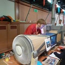
For the light source we shone a 3W LED bike light into the focusser of a telescope to create a search-lamp-like beam. I realised that the camera would struggle for brightness so I went for high intensity focussed in a narrow beam to maximise light hundreds of meters away. I 3D printed a clip to secure the bike light but tape would probably have been fine. Shining it 15m down my garden the beam was still painfully bright and had not diverged too much.
Circular object
To get good resolution with easy set-up I recommend an object 50-100mm in diameter.
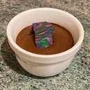
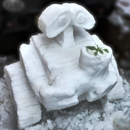
I prepared a few objects, but only ended up using the disc removed from a broken 2.5" hard drive as it seemed the best edge. My pizza cutter practically volunteered for the job though because the wheel fell off 2 days before testing and I'm confident it would have worked just as well. My third object was a 50mm ball bearing which has the best quality of edge but is very heavy so difficult to mount. I did balance it on 3 nails for a test but it wasn't very stable so I decided against it.
Stencil
I made various stencils by laser cutting some old cardboard folders. I then spraymounted them to scrap clear perspex, trying to avoid the holes where possible. The best two stencil types were smiley faces and Instructables robots, each cut in 1", 2" and 4" scale
Flat dark space
I live in Cambridgeshire, UK so flat isn't a problem. I picked the cycle path along the guided busway as a dark, straight unobstructed place. When we got there at night we did find there were solar lights at the side, which is probably why our images were a bit washed out, but it still worked well enough.
Step 4: Setting Up the Light


Using a telescope to direct our light beam meant we had really easy fine adjustment of the direction. We set up the tripod on a bridge and it shone down at the cycle path underneath. Fortunately, not a single cyclist came while we had it there (as it was painfully bright to look at and destroyed all night vision). We then clamped the stencil in front of the telecope using retort stands attached to the railings of the bridge.
Once we had set up the other parts, we fine tuned the direction of the beam.
Shining your light in the right direction, with the means to attach your stencil in the path of the beam is all that you need to do here.
Step 5: Setting Up the Disc 'lens'


The disc needs to be far from the light source in order for the incoherent light to diffract. It needs to be at least 100m away (depending on scale of disc and light source); we placed ours 200m away.
We taped the disc (with the central hole covered with aluminium tape) to some wire which we wraped around a piece of wood and clamped in a tripod. We needed this to be high to keep the shadow high enough for the camera, but you can choose your mounting technique based on the space you are using. Mount the disc as close as you can get to perpendicular to the beam, in a position that allows you to place the camera in the shadow tens of metres away.
Then follow the shadow to set up the camera...
Step 6: Position the Camera


To find it easiest to get the image I recommend that the camera is placed 20-50m away from the disc, in the centre of its shadow. Further is higher magnification but harder to align, very close reduces the brightness significantly.
The easiest way to do this is to walk to the distance you want to set the camera at, and get a friend to shine a torch from near the disc. Line up the light source with the torch and then get them to turn the torch off. Now if you slowly move your arm around you should find the shadow of the tripod. Follow the shadow until you have found the shadow of the disc with your hand. This is where you need to put the camera sensor.
Take the lens off the camera, if you haven't already, and turn up the sensitivity to max ISO and long (10 seconds? - depends on light source brightness) shutter. Adjust the tripod until the camera sensor sits centrally in the shadow. Adjust the exposure settings until the shadow is dark grey. If you are closer to the disc this will be easy, but further away the shadow is larger and you may not be in the exact centre. The tripod we used had a handle to wind the camera up and down vertically which proved very useful. We wound the camera up, found the centre of the top of the circle using the image of the shadow on the camera screen. We then wound down the camera to the bottom and then wound half way back up. This made it easy to find the exact sensor but trial and error also works.
In the camera image you should see a faint lighter area the shape of your light source. Because we used a telescope this was a light circle with a dark circle in the middle (shadow of the secondary lens). Incredibly in the image we took you can actually see the supports that hold the primary mirror (called the spider). These are faint because the theoretical limit of resolution for our set-up was 7 times the 0.5mm thickness of these supports so their contrast is reduced by a factor of 7 in an already faint image.
If your light source has less features to see you'll want to add a shape to truly believe you have an image...
Step 7: Seeing Small Things From Far Away


Adding stencils allows you to make the light source more interesting to look at. The bridge we shone our light from had a railing to which we clamped a retort stand that held the stencils. By spray-mounting different card stencils to perspex we had simple flexible means to modify the light shape.
Performance
The smallest robot in the photos is 1 inch (25mm) tall. In angular terms from the disc, it is 26 arcseconds (where an arcsecond is 1/3600 of a degree!) tall. That is about the size of Mars when viewed from Earth (at its closest). The larger robot is 2 inches (50mm) or 52 arcseconds, and about the size of Jupiter viewed from Earth at its closest. If for a moment we imagine being able to point this set up at the heavens we would get great magnification and the resolution would be comparable to a decent beginner's telescope.
How different distances affect the performance
The magnification of the image is the ratio of (distance camera to disc)/(distance disc to object) so every millimetre in the object gives 0.2mm at the image sensor. Unlike a lens, increasing magnification doesn't lower the intensity. However increasing the magnification won't add detail beyond the diffraction limit
The diffraction limit resolution at the object is 2.44*(distance disc to object)*(Wavelength of light)/(Disc diameter). For us this is 3.9mm.
If you want a comparison with a camera lens, the equivalent focal length is (distance camera to disc)*(distance disc to object)/(distance camera to object), in our case 33 metres.
If we upscaled to a 3m disc we could exceed the resolution of Hubble. In practice the limitations are ease of aiming (especially as earth is spinning) and atmospheric perturbations, neither of which are challenging in space (over and above the extremely challenging basics of anything working in space!). Making a large, accurate disc is substantially simpler than making a precision ground 3D surface for a mirror or lens, so hundred plus metre apertures become possible. The only drawback with the simple Aragoscope is the reduced light collection compared with a traditional telescope, which makes imaging distant stars difficult. Therefore the plan NASA is exploring has an Aragoscope as a primary aperture, with traditional lenses collecting the light that would form images at all the different positions along the central axis, such that a brighter image can be formed.

Runner Up in the
Space Challenge

Participated in the
Trash to Treasure

Participated in the
Pocket-Sized Contest


