

Introduction: Arduino Games Console - With Multiple Games
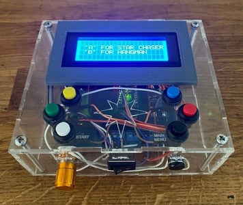


I've been aspiring to build a self-contained Arduino based games console for a while. The console had to be battery powered, re-chargeable and have more than one game. The purpose of the project is to show the young people I come across that coding and electronics is accessible and you can create something fun and useable with some effort. I made the enclosure clear so that the inner workings can be seen while you are using it and to help lift the veil of obscurity hiding the inner workings of modern day electronics. This is not a beginner project but I am going to include the Arduino Code, the gerber files for the pcb, the schematics for the enclosure and any 3d print files so that you can build it as if it was a kit.
Supplies


I tend to have many of the materials in stock however you can get everything from ebay, amazon or preferably you local electronics supplier.
Here's a extensive list of the tools and materials you will need to build this project:
Materials:
- Arduino Nano (328p) x 1
- Header pins 15 pin x 2
- 18650 Lithium Battery x 1
- 18650 battery holder x 1
- TP4056 USB 18650 charge controller x 1
- MT3608 Boost Converter x 1
- 5mm PCB Screw Terminals x 20
- 12mm diameter spring return pushbuttons x 6
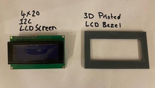
- 4 x 20 LCD Display
- LCD Bezel x 1
- M3 x 15 Screws to Mount the LCD Display x 4
- M3 nuts and washers x 8
- M4 x 16 Nylon Screws to Mount PCB x 4
- M4 Nylon nuts and Washers x 8
- M4 x 60 Stainless steel Screws x 4
- 3mm Clear Acrylic Sheet 400mm x 600mm x 1
- 5k potentiometer x 1
- Rocker switch for power x 1
- 12mm diameter passive buzzer x 1
- PCB Slide Switch x 1
- Solder
Tools:
- Soldering Iron
- M4 Tap
- Laser Cutter
- 3D Printer
- PC or Laptop
- Screwdrivers, pliers, cutters etc.
Step 1: Enclosure

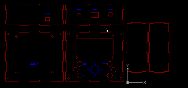

The enclosure was made using laser cut 3mm clear acrylic sheet. I use an online tool called makercase.com to design boxes for me. This is an excellent resource for saving time when designing laser cut boxes as it does much of the hard work for you. Once you've designed to outside of your box you can then download the CAD files and then use the 2D CAD package of your choice to add any cut outs for buttons etc. AutoCAD LT is the type of CAD package ideal for adding all the extras to the enclosure. I tend to ensure I use different drawing layers for the outline to be cut, the text and any engravings so that when you open the drawing on the laser cutter software you can set the laser power up for the different layers together with the order in which you want to cut or engrave, for example you normally want to engrave any images or text before you cut so that the material doesn't move.
The 4 screws in the corner of the box pull the box tight together so there is no need to glue the box. I did this partly because I wanted the console to be repairable and modifiable in the future. The bottom hole is cut to 3.5mm and then treaded with a 4mm tap as shown in the image.
The enclose CAD file is attached if you want to use it.
Attachments

Step 2: LCD Bezel


I've included this section because this is another area of the project designed to be re-used with other projects. The bezel really tidies up projects that use LCD screens. I designed it using Fusion360 then 3D printed it using my Ender 3.
The bezel is attached to the enclosure using strong double sided tape.
I have included the STL file for anyone who wants to 3D print their own LCD bezel.
Attachments

Step 3: Electronics and PCB
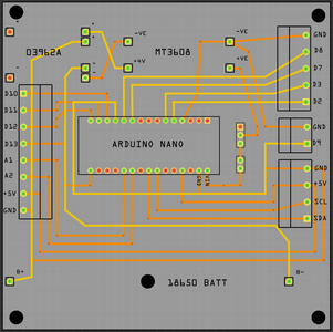


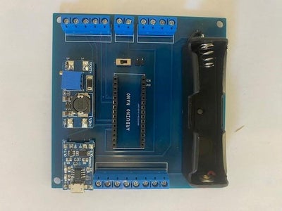

The PCB serves to purposes, firstly to breakout the connections of the Arduino NANO to allow easy connection to all the enclosure mounted Inputs and Outputs and secondly to facilitate the battery and charging hardware.
If you look closely at the PCB you will see there are several unused connections. This is because I wanted to make sure the PCB could be used for other purposes in the future. I thought a self contained rechargeable Arduino Nano based PCB would be useful for all sorts of projects. I made sure I had access to pins on each of the ports (for future interrupts) plus access to SPI in addition to I2C.
Once you have your PCB you just need to solder all of the components to it as shown in the photo's.
The battery is is lithium 18650 battery. I prefer to use these batteries and to me they feel safer than the soft cased lithium polymer batteries. The TP4056 USB charge controller is used to charge the battery via a USB connection. This brings the battery up to about 4 volts which is not enough to power the Arduino Nano. The output from the charge controller and the battery connections is then fed to the MT3608 Boost Converter which you then set the output to the desired voltage, I used 7 Volts.
VERY IMPORTANT!!!
Make sure you set the output of the boost converter to a sensible value before connecting the Arduino Nano because they boost converter can supply up to 28 Volts. The Arduino NANO has an on board voltage regulator but the input voltage should be 7-12 volts. If you provide a high voltage to the Arduino Nano you will kill it which is not good during a chip shortage!
I had the PCB made by JLC PCB but you could easily have it made by PCBWay or one of the other manufacturers. It would not be too hard to make this board yourself by etching copper clad board (far less messy to get it made though). I have attached the fritzing file if you want to make the pcb.
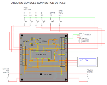
The schematic above shows how all of the the Input and Output devices are connected to the PCB terminals.
Attachments
Step 4: The Games

As I mentioned previously I wanted to make a console with at least two games. I decided to have a go at writing my own game called Star Chaser for the first game and then for the second game I used a version of hangman I found while hunting through the internet.
The challenge of making a single game console is simple but making a 2-game console is harder especially only using an Arduino Nano.
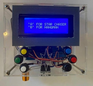
When you first turn on the console you are given the option of choosing "A" for Star Chaser or "B" for Hangman.
Star Chaser
I wanted to make a simple game that didn't involve shooting or killing or blowing up anything or anyone as there's too much of that in the real world at the moment. With Star Chaser you are on an explorer with the aim of travelling through space to observe one hundred stars. As the stars come towards you you have to move into their path by pressing buttons "C" to go up and "D" to go down. You need to keep pressing the button to stay in the desired position otherwise you will return to the centre position. Each time you observe 10 more stars your ship moves one position to the right so the stars come at you faster. If you miss observing a star you need to start again. Once you have observed 100 stars your mission is complete. Observing 100 stars is quite challenging!
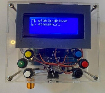
Hangman
Hangman is simply the classic game of guessing the word. When you enter the game you scroll right through the alphabet with button "A" and left with button "B" you select the letter by pressing the "Start" button. If you have guessed correctly it fills in the letters where the blanks are below. If you guess wrongly then another part of the hangman is drawn and you loose a life. Whenever you guess a letter if is replaced with a "*" when you scroll to this letter again. You win by guessing all the word before all your lives are lost.
Step 5: The Code

The code was probably the hardest part of this project. There's about 900 lines of code for this project so I'm not going to go into every detail however I will go into a couple of areas. Firstly I will show how I made custom characters for the LCD Screen and Secondly I will show some of the interrupts.
Custom LCD Characters
Custom Characters are a cool way of making a game on an LCD screen. The first thing you do is design your custom character on an 8 x 5 bit map. below is the code I used for the bitmap of the "Star Ship".
byte starShip[] = {
 B11111,
 B10001,
 B11111,
 B11111,
 B10101,
 B10101,
 B00000,
 B10101
};
If you use your imagination you can see the shape of the Star Ship used in the game as the 1's are filled in and the 0's are not filled in. You do not need to use binary numbers for this and you could convert to Hex, so 11111 would be written as 1f in Hex (I have used hex for the custom characters used in the hangman game).
Once you have designed your characters you need to create them. You are really only allowed to use 5 custom characters with the I2C Library but I found that so long as I re-create the characters I want to use when I start the game I want then I can trick the code to let me use as many as I want. Here's the code for creating the character for the starShip.
lcd.createChar(3, starShip);
The code then reads whether the "up" or "down" button has been pressed and draws the starShip in the correct position for the game play using the following function.
void drawman() {
 lcd.setCursor(wall, level);
 lcd.write(byte(3));
}
Using Interrupts
Interrupts are essential if you are writing a button operated video game, especially an action based game where you want the processor to react to the button press regardless of what else is happening. I used interrupts liberally in this game for both moving the Star Ship in Star Chaser and then for returning to the main menu with the main menu button. The "C" and "D" buttons used the two hardware interrupts available on the Arduino Nano on pins D2 and D3. However I'd run out of hardware interrupts for the main menu button so I used a pin change interrupt.
To enable pin 11 to be the pin change interrupt to return to main menu I had to enable the interrupt with the following code in the setup function:
 // Enable PCIE0 Bit0 = 1 (Port b)
 PCICR |= B00000001;
 // Enable PCINT18 & PCINT23 (Pins D11)
 PCMSK0 |= B00001000;
The following function is then executed when the button on pin 11 is pressed.
ISR (PCINT0_vect)
{
 // Port D Interrupt occured
 // Check if this was D11
 if (digitalRead(menu_button) == LOW) {
  //Pin D7 triggered the ISR on a Falling pulse
  returnFlag = 1;
 }
}
I don't return directly back to the main loop function, rather I set a returnFlag to "1". This is then checked at every loop in the programme. If the returnFlag changes to "1" then the loop is exited. As this occurs in every loop in the programme it eventually cascades back to the main loop.
Here's a brilliant tutorial on interrupts if you want to know more: Using Arduino Interrupts - Hardware, Pin Change and Timer (dronebotworkshop.com)
The code for the hangman game is is based on the code by Dan Wagoner, his brilliant github page is here: https://github.com/danwagoner/hangman. I had to modify it a bit to work with buttons and to fit in with a multi game console.
Attachments
Step 6: Final Testing and Conclusion
The best way to see the finished product is to look at the two videos of me playing the games.
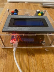
To charge the console you just plug a USB Micro B cable in the back as shown in the image, it's fully charged when the LED light turns from red to blue.
The battery seems to last for absolutely ages, we've not had to charge it up after many many games so the console would be good for a long car journey.
I am currently thinking of another simple game to add to this console and some other uses for the PCB.


