

Introduction: Serial Controlled Arduino Orb


When I first saw the Ambient Orb from Ambient Devices, I was pretty impressed. They describe it as a glass lamp that uses color to show information. Any sort of status could probably be displayed with an orb using color and flashing/pulsing patterns. I work with a team of developers, and I wanted an orb to display information about the state of our software. Specifically, did our software pass all the automated tests and is it ready to move to the next step in the process.
The orbs from Ambient are really cool, and I really wanted one. Unfortunately, they are $150, and you need to spend $7/month to control it.
Requirements
I figured I could build one myself. I had several requirements:
*No monthly fee - I didn't want to pay a monthly charge. I figure we'll use it for years, and $7/mo would really add up.
*Controllable via serial port - PCs at my company are pretty locked down. I can't install USB drivers, but I can access the serial port.
*Bright - I want people to be able to see this thing. It needed to be bright.
So, I set out to create my own orb.
Step 1: Ceiling Light Fixture


I went to Home Depot looking for a ceiling light I could repurpose. I looked for the whitest and roundest ceiling light I could find. The perfect light was only $6. SKU 385 303 .
The glass globe of the ceiling light has some coating on the inside to diffuse the light. It turned out that this coating was perfect. You don't see the individual LEDs. Instead, the whole globe just glows.
I needed to replace the 110V AC light bulb socket with 12V LEDs. The light socket was held in place with two clips. It only took a few seconds to remove the socket and fixture was ready to get some LEDs.
Step 2: LEDs


The next step was to find some LEDs to light the orb. I found the Satellite Module at Sparkfun Electronics . This array has 4 red LEDs, 3 green LEDs, and 3 blue LEDs, and it's really bright. While working with it on the bench, I usually put three our four layers of paper over it because it hurts my eyes. Each color requires 9 - 10V at 100mA, so I'm powering it with a 12V wall wart .
I didn't actually mount the satellite module. I connected the satellite with fairly heavy wire. I can bend the wire where I want it, and the satellite just stays there. To prevent any short circuits, I added a little round piece of cork I had laying around.
Step 3: Arduino Control

I love Arduino because it's so fun and easy to program. The Arduino lets me control the red, green, and blue LEDs individually. To do that, I define which pins to use, and then tell the Arduino to use those pins for output.
//DEFINE PINS
const int RED = 9;
const int GREEN = 10;
const int BLUE = 11;
//SET ARDUINO R,G,B PINS FOR OUTPUT
pinMode(RED,OUTPUT);
pinMode(GREEN,OUTPUT);
pinMode(BLUE,OUTPUT);
//PWM TO LIGHT THE LEDS
analogWrite(RED,128);
analogWrite(GREEN,0);
analogWrite(BLUE,255);
LEDs can't be dimmed. They are either ON or OFF. The Arduino can use a technique called Pulse-Width Modulation (PWM) to very rapidly switch the LEDs OFF and ON. The more they are off, the dimmer they appear. To display a color like purple, set the RGB color values to something like (125,0,255).
The red is set half way using PWM
analogWrite(RED,128);
the green is completely off,
analogWrite(GREEN,0);
and blue is completely on
analogWrite(BLUE,255);
It's pretty tough to format code for an instructable. Attached is a zip file of my code.
Attachments

Step 4:

The Satellite Module requires 10V and 100mA. Unfortunately, the Arduino only supplies 5V and up to 40mA on each pin.
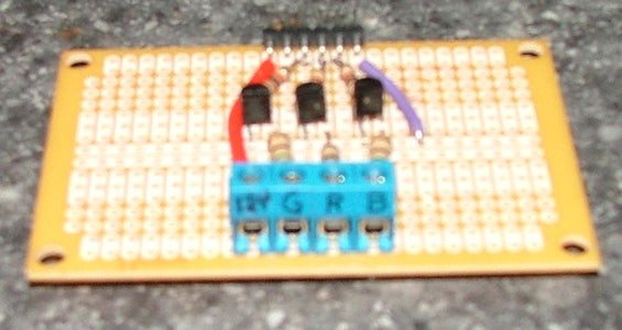
The Satellite Module calls for 10V on the red, and 9V for the green and blue. It's easy enough to turn the 12V from the wall wart to the correct voltage by adding series resistors for each channel.
The LEDs shouldn't stay on all the time. To switch them off and on, I use a 2N2222 NPN transistor. A transistor is like a little light switch. When current is applied to the base (B) of the transistor from the Arduino, current flows from the collector (C) to the emitter (E). So, when the Arduino pin is turned on, current flows from the 12V wall wart, through the Satellite Module, through the series resistors, through the transistor, to ground. When the Arduino pin is turned off, the transistor is turned off, and current stops flowing through the Satellite Module LEDs. With the analogWrite function tells the Arduino to use PWM to switch the transistor on and off up to 500 times per second, making the LED look dimmer than it would look if it were constantly on.
Step 5: RS232 Serial Control
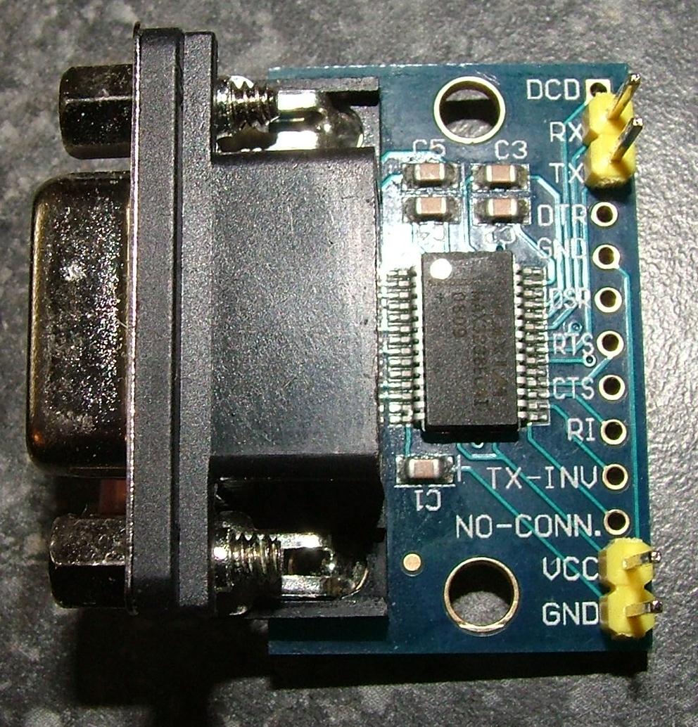
One of the requirements I had was to use the COM1 serial port on the computer to control the orb, instead of using USB. You can't connect the serial port of the computer directly to the Arduino. The serial port supplies +/- 7.5V, and the Arduino expects 0V to 5V. To make the translation, I used the MAX232 IC. I got a nice RS232 to TTL adapter from RobotShop.com .
The TX (transmit) from the adapter is connected to the RX (receive) pin 0 on the Arduino. I don't use it, but it just felt right to connect the RX from the adaper to the TX pin 1 of the Arduino.
Step 6: Enclosure

I made an enclosure from MDF . I added an illuminated toggle switch from RadioShack. The base of the ceiling light is mounted on the outside of the enclosure, and the wires connect from the transistor circuit, through the enclosure, through the base of the ceiling light, to the satellite module.
Step 7: Arduino Code

Here is a chunk of the code. It isn't very readable, so I'm not including it all here. Download the zip file an look at in in the Arduino editor.
------------------------------------------------------------------------
const int RED = 9;
const int GREEN = 10;
const int BLUE = 11;
const unsigned long tenMinutes = 600000; //TEN MINUTES IN MILLISECONDS
int incomingByte; //BYTE RECEIVED FROM SERIAL PORT
void setup() {
//SETUP SERIAL
pinMode(0,INPUT); //SERIAL INPUT ON PIN 0 (RX)
pinMode(1,OUTPUT); //SERIAL OUTPUT ON PIN 1 (TX)
Serial.begin(9600);
//SET ARDUINO R,G,B PINS FOR OUTPUT
pinMode(RED,OUTPUT);
pinMode(GREEN,OUTPUT);
pinMode(BLUE,OUTPUT);
//DO A LITTLE LIGHT SHOW WHEN STARTING
CrossFade(000,000,000,000,000,255,5000); //OFF TO BLUE
LightShow(4000); //ONCE SLOW
LightShow(2000); //ONCE MEDIUM
LightShow(1000); //ONCE FAST
LightShow(1000); //SECOND TIME FAST
CrossFade(000,000,255,000,000,000,1000); //BLUE TO OFF
}
void loop() {
/*************************************************************
* B - Building
* S - Successful build - Future S[,mp3 filename]
* F - Failed build - Future F[,mp3 filename]
* C,RRR,GGG,BBB - display a Color
* O - Off
* P,mp3 filename - Play mp3 (Future)
* X,RRR,GGG,BBB,RRR,GGG,BBB,tttt - cross fade color to color
* L - Light show
*************************************************************/
if (Serial.available() > 0) {
incomingByte = Serial.read();
switch (char(incomingByte)) {
case 'B': //BUILDING
Building(millis() + tenMinutes);
break;
case 'S': //SUCCESSFUL BUILD
SuccessfulBuild(millis() + tenMinutes);
break;
case 'F': //FAILED BUILD
FailedBuild(millis() + tenMinutes);
break;
case 'C': //DISPLAY A COLOR
delay(50); //DELAY TO ALLOW THE DATA TO BE SENT
SetColor(GetNumberFromSerial(3),GetNumberFromSerial(3),GetNumberFromSerial(3));
break;
case 'O': //ORB OFF
SetColor(0,0,0);
Serial.flush();
break;
case 'P': //PLAY MP3
delay(50); //DELAY TO ALLOW THE DATA TO BE SENT
PlayMP3();
break;
case 'X': //CROSS FADE
delay(50); //DELAY TO ALLOW THE DATA TO BE SENT
CrossFade(GetNumberFromSerial(3),GetNumberFromSerial(3),GetNumberFromSerial(3),GetNumberFromSerial(3),GetNumberFromSerial(3),GetNumberFromSerial(3),GetNumberFromSerial(4));
break;
case 'L': //LIGHT SHOW
CrossFade(000,000,000,000,000,255,5000); //OFF TO BLUE
LightShow(5000);
CrossFade(000,000,255,000,000,000,5000); //BLUE TO OFF
break;
default: //UNHANDLED
Serial.flush();
}
}
}
Attachments
Step 8: Parts

I like to get small batches of the little parts like resistors and transistors from eBay. If you're ordering more, Mouser Electronics is great.
Here are the special parts that are a little more difficult to find.
Ceiling light - SKU 385-303 - Home Depot - $6
Satellite Module - Sparkfun - $17
Arduino Uno - $30
RS232 to TTL adapter - RB-Dro-05 - RobotShop - $13
Toggle switch - 275-0010 - RadioShack - $3
12V wall wart - Sparkfun - $6
Step 9: Sending Commands to the Orb

The final step is to connect the orb to your PC using a serial cable. I picked up a 25 foot serial cable for $3.42 and a F/F gender changer for $0.86. MonoPrice.com is a great site for stuff like this.
Once it's connected, you can send commands from the PC to the orb. The easiest way is from a DOS prompt. To start the build, type
ECHO B > COM1
That means to send the letter "B" to the COM1 (serial) port. If you have more than one serial port, adjust accordingly.
As the code is written, it has a bunch of functions that are initiated with a single character.
B - Building
S - Successful build
F - Failed build
O - Off
L - Light show
There are also some functions that require longer strings to be sent to the serial port. For example, to change the orb color to a mix of red and blue...
ECHO C,255,000,150 > COM1
Here are the rest of the commands the orb understands:
C,RRR,GGG,BBB - display a Color
X,RRR,GGG,BBB,RRR,GGG,BBB,tttt - cross fade color to color
P,mp3 filename - Play mp3 (Future)
S - Successful build - Future S[,mp3 filename]
F - Failed build - Future F[,mp3 filename]
Step 10: Orb in Action
Failed build:


