

Introduction: Arduino Pedometer Watch, With Temperature, Altitude and Compass!


UPDATE: CHECK OUT MY OTHER TWO PROJECTS >>
SweeperBot - Roomba-like Robot With Bluetooth
Alarm Clock with Infrared and Bluetooth Speakers
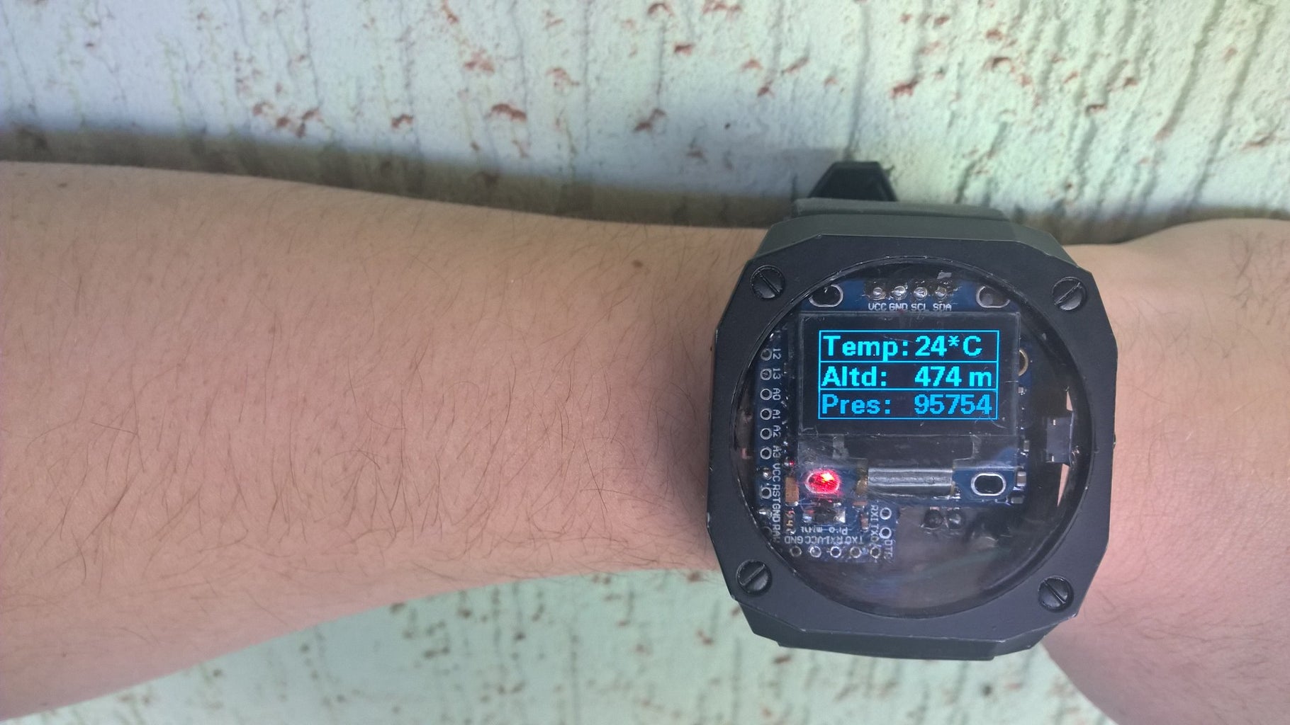
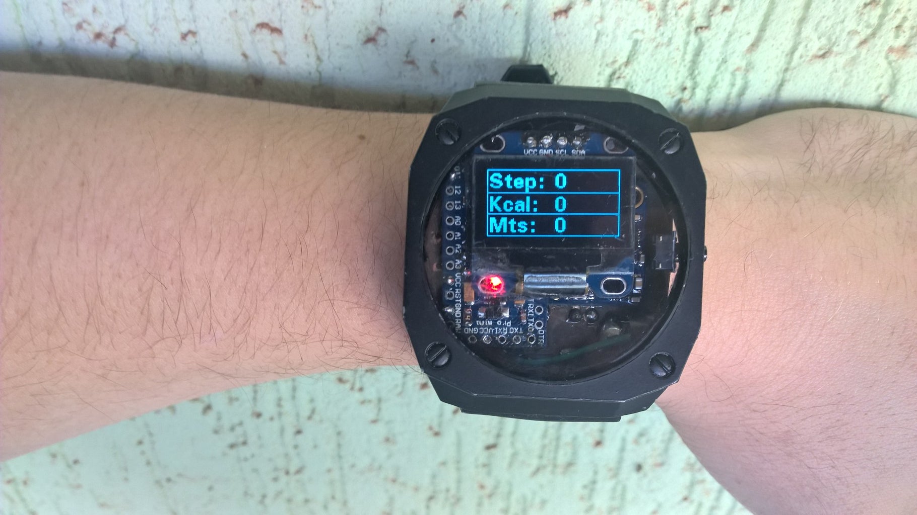
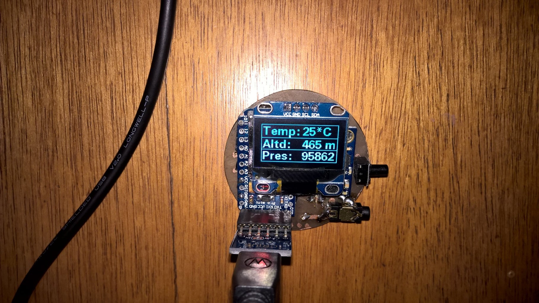
Hi folks! Last few days I've been obsessed with the idea to make my own watch from arduino parts, but something cool I could use and say I did it myself. So I found out there was a sensor board (commonly named GY-87) which had three sensors on it: HMC5883L (compass), BMP085 (pressure, altitude, temperature) and MPU6050 (accelerometer and gyroscope). With it, via I2C, I could add an Arduino Pro Mini, and an I2C Oled Display and make a watch capable of having all this information, plus a pedometer (by analysing accelerometer data).
Cool enough, it was incredibly easy to make, and you will just need some cheap parts, a small amount of Eagle PCB knowledge, some skill on making your own PCB board, and preferably a cheap watch to unmount and get the bracelet / carcass.
Before start, I'll just post some pictures of previous versions I made so you can have an idea of the challenges you'll face, and stuff you can add if you like. Let's get going!
Observation: forgive me if my english is not good enough, this is not my native language, for I am brazilian. XD
Step 1: Previous Versions
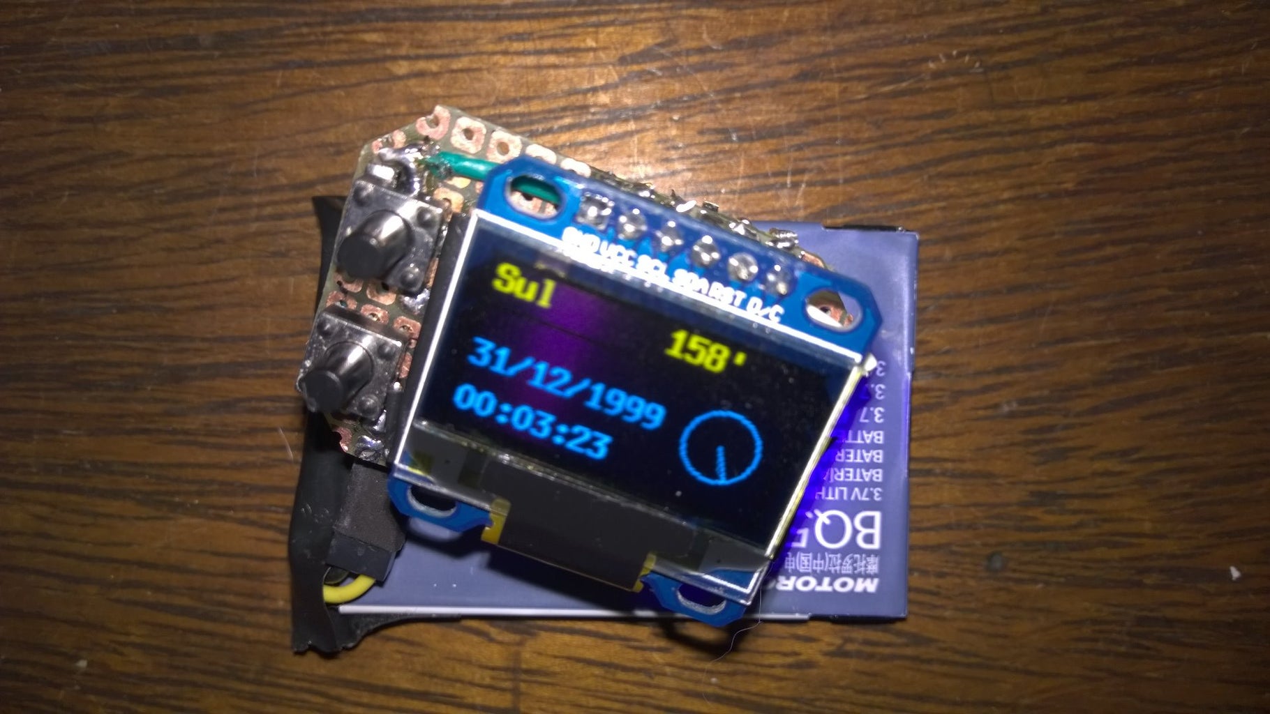


There were two previous versions of the watch. The first one was an attempt to put compass and bluetooth together. It succeeded. The watch was small in size, but too thick. The first three images are it. It could communicate with my Windows Phone via bluetooth, get automatically the time and date, and also my next calendar appointments and display them. It was also sending many times per second the current compass position, and the phone would display it. Yeah, I had to make the WP app. I think I have it here, so I'll post it with the instructable. However there were some problems with the Project:
- The bluetooth consumes A LOT of energy, and the battery lasted just for an hour or so;
- There was no real advantage in using the bluetooth, because the date and time you could put also using the buttons, and if the battery could last a day long, you would charge before running out, so you wouldnt have to put date and time again;
- The calendar thing was great, but was kind of useless, because you could always check it on the phone, and as the watch had limited memory space, you couldnt download all the calendar;
- Plus, each alteration of calendar would require to sincronize again;
- Sending the compass back to the phone and spinning a compass on the display was great too, but of course useless, because the watch already did that;
- The watch had resistors on each button, something I found out later that was useless, because arduino already has pull up resistors on each digital input pin, you just have to turn it on;
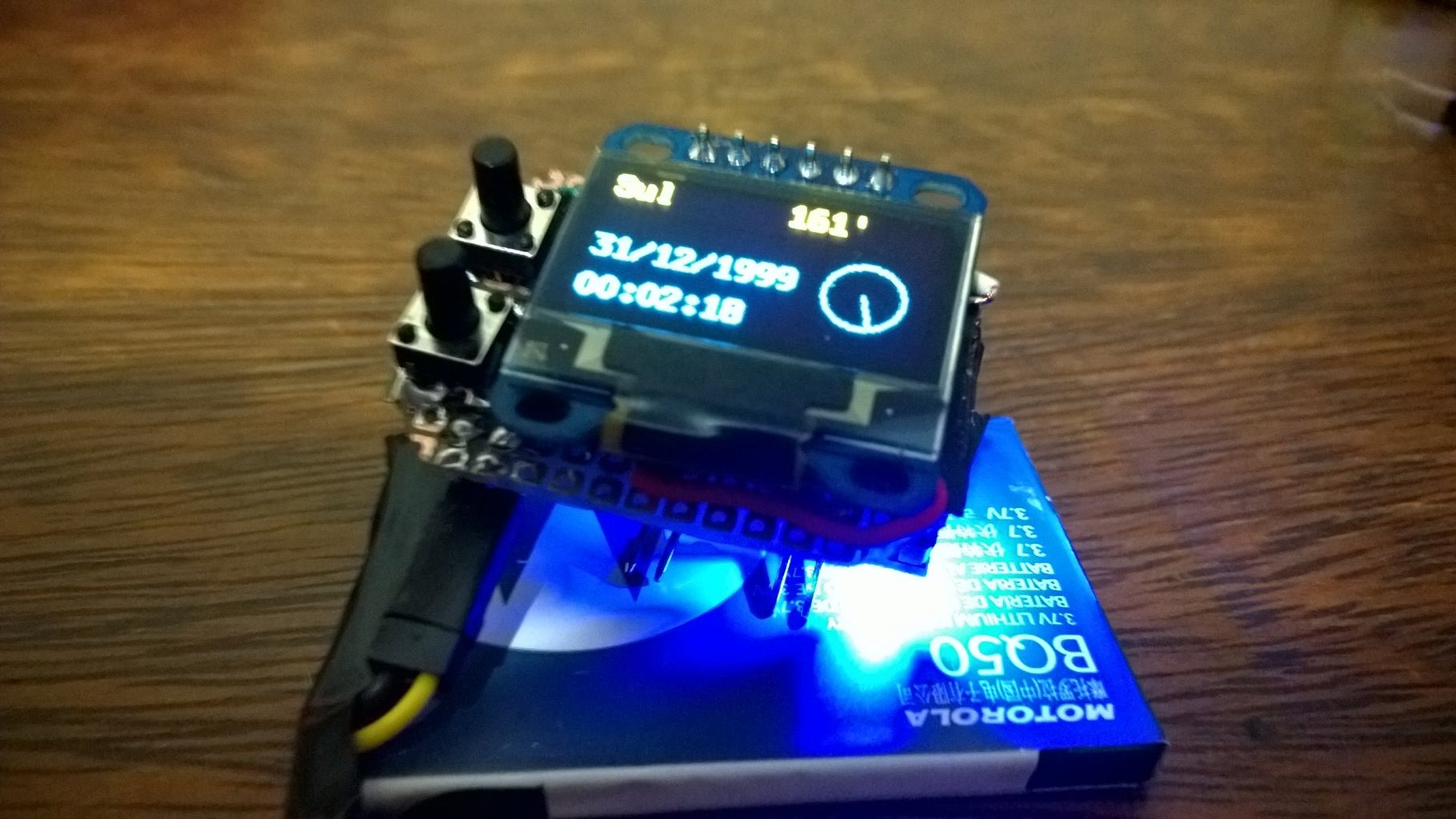
So I tried to make another with the bluetooth, but one that you could turn it on with a switch. It turned out that switching it on and off resets the arduino . I figured out that I didnt need the bluetooth, so I made a second version, with an MPU9150 (compass, accelerometer and gyro). The second version is on the next 13 images. It was a pretty better unit, also with two buttons (I still used resistors on them), larger in size, and less thicker than the original. The battery was smaller, and I managed to make a carcass to wear it. It got kind of steampunk look, but wasnt something I would wear on the street (lol). The battery lasted 14 hours! Amazing! Problems as follow:
- I could have desoldered the two leds that there are on the boards: one on the arduino and one on the MPU9150 to spare energy;
- There was no need to use resistors;
- There was no need to have two buttons, because I could implement via software two functions to the same button;
- It was too thick;
- The carcass wasnt great, and was too big;
- The charging was made via a two pin conector on the side, and if just one time you got confused and put the conector inverted could burn the system - it had to be fool proof;
- I glued everything with silicone glue, however I found out silicon glue oxidate the copper and the tin, conducting current, so it was a problem;
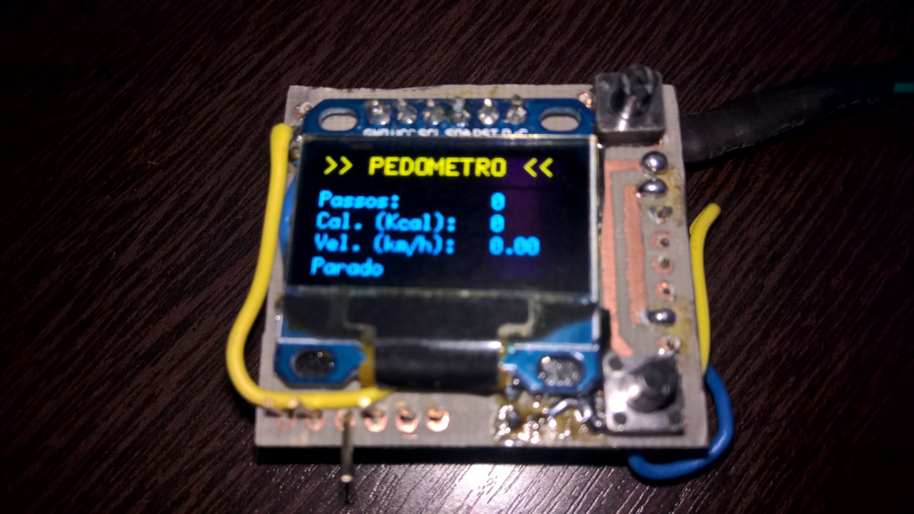
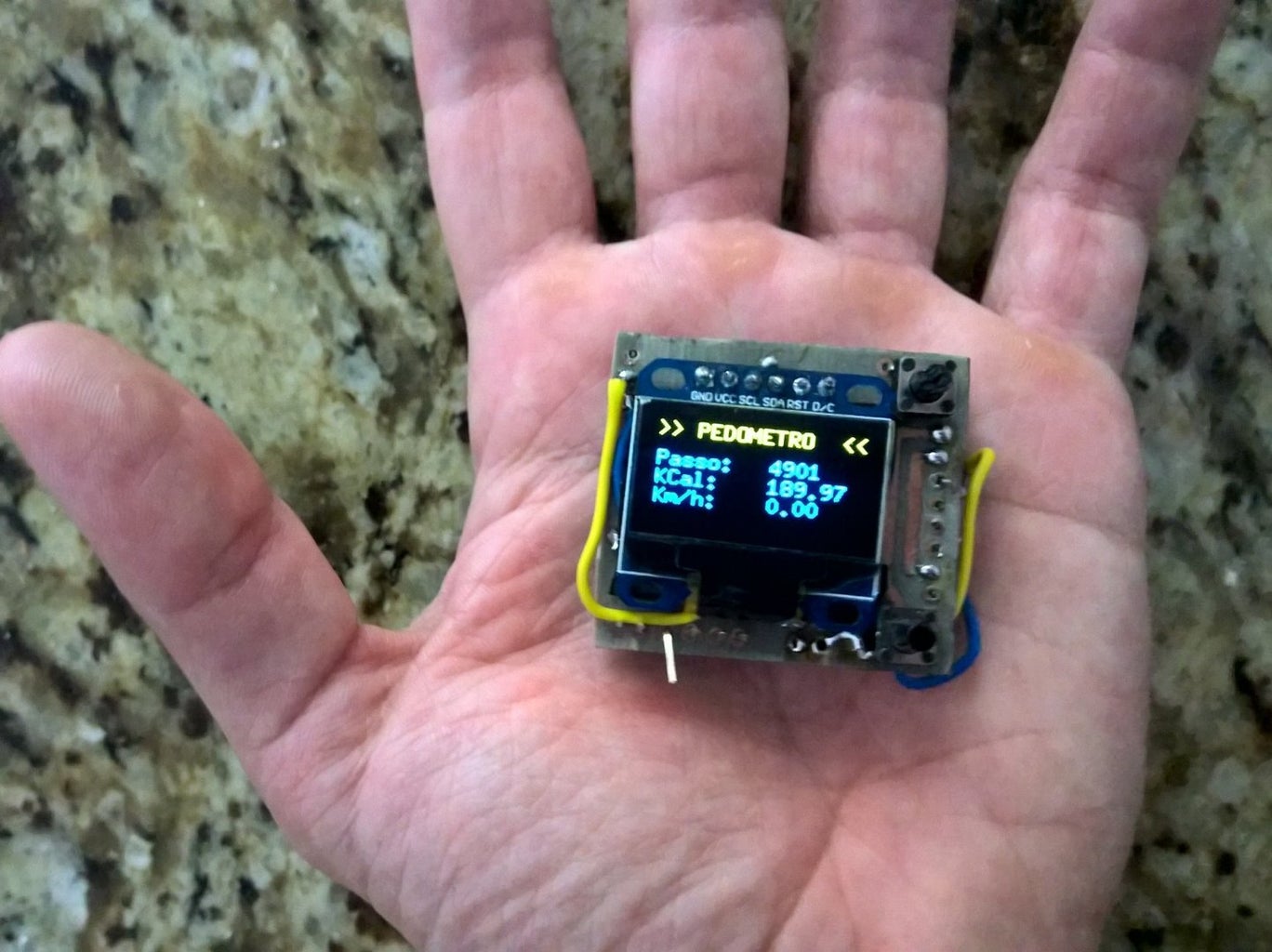
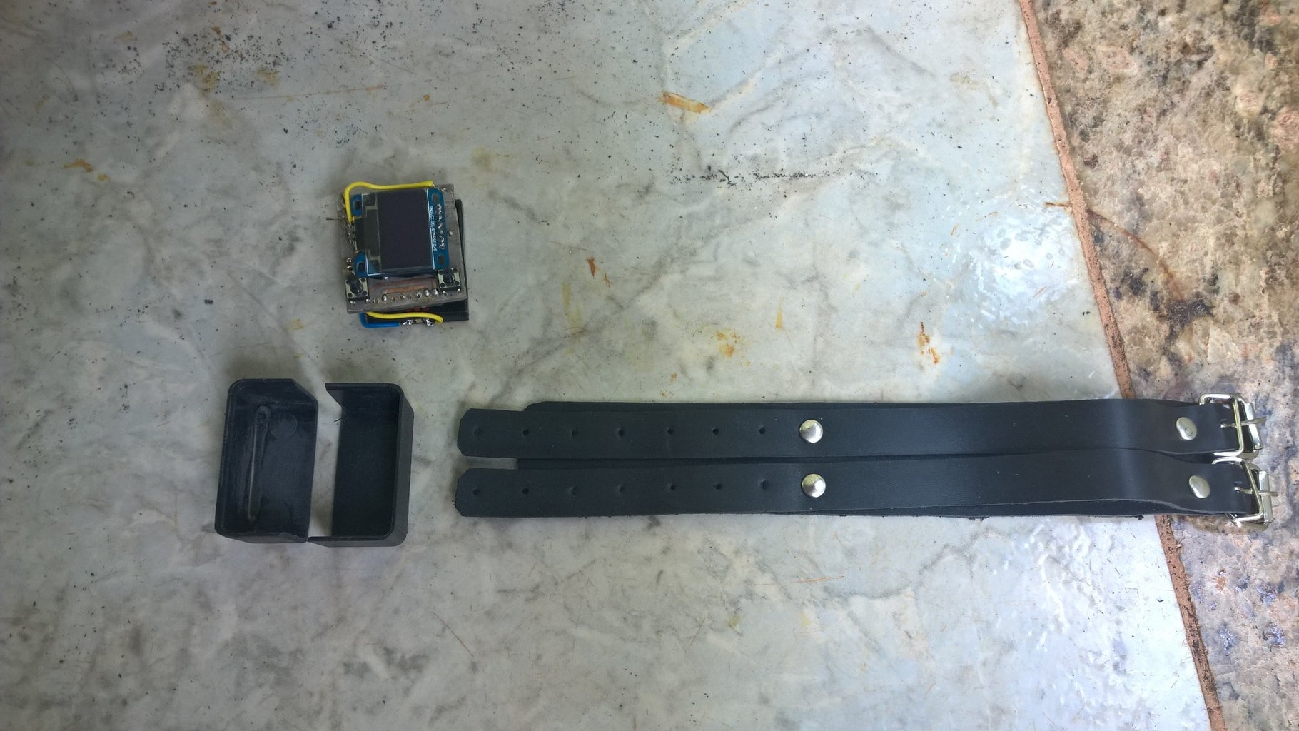
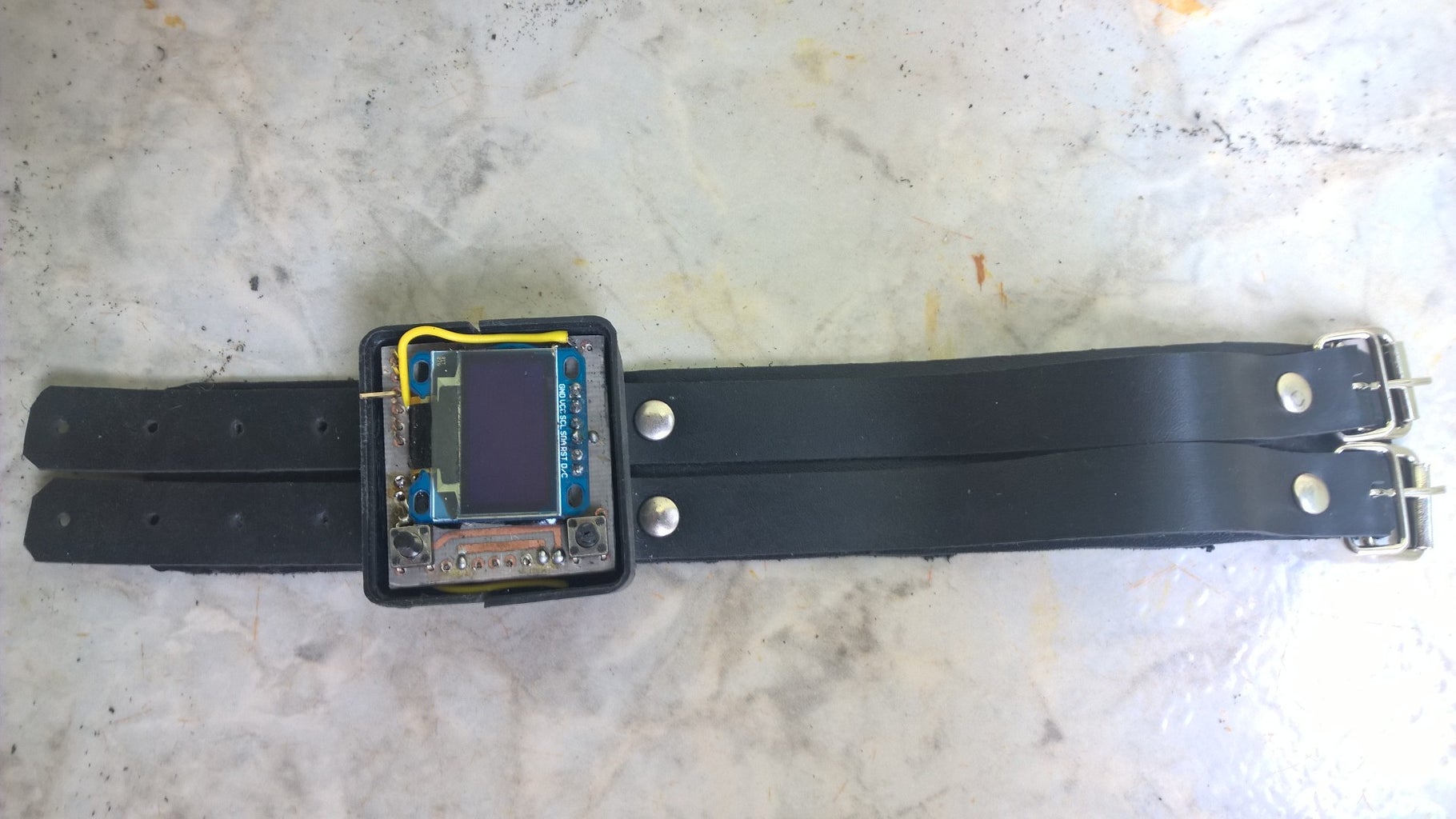
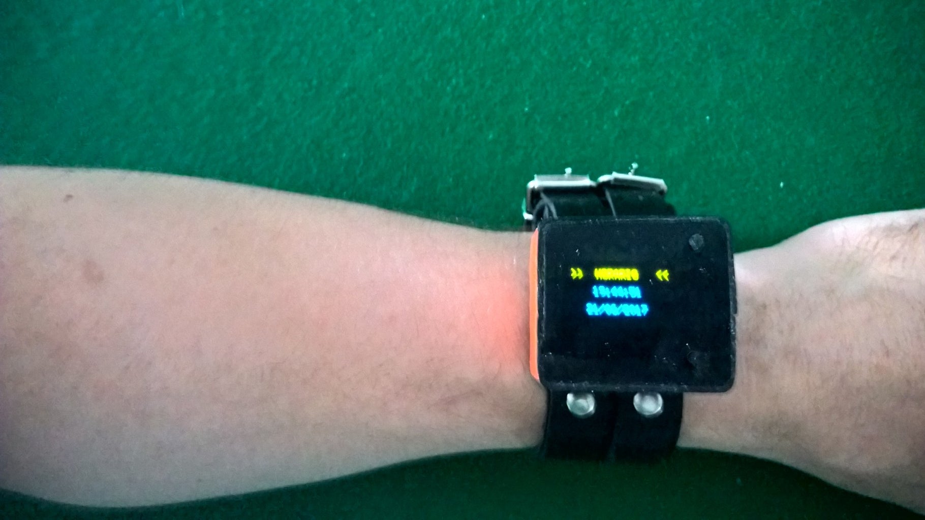
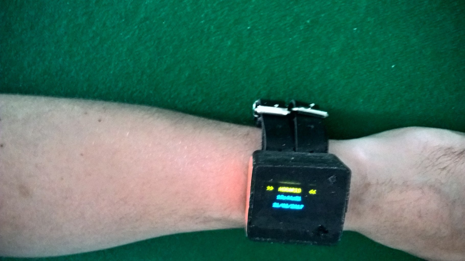
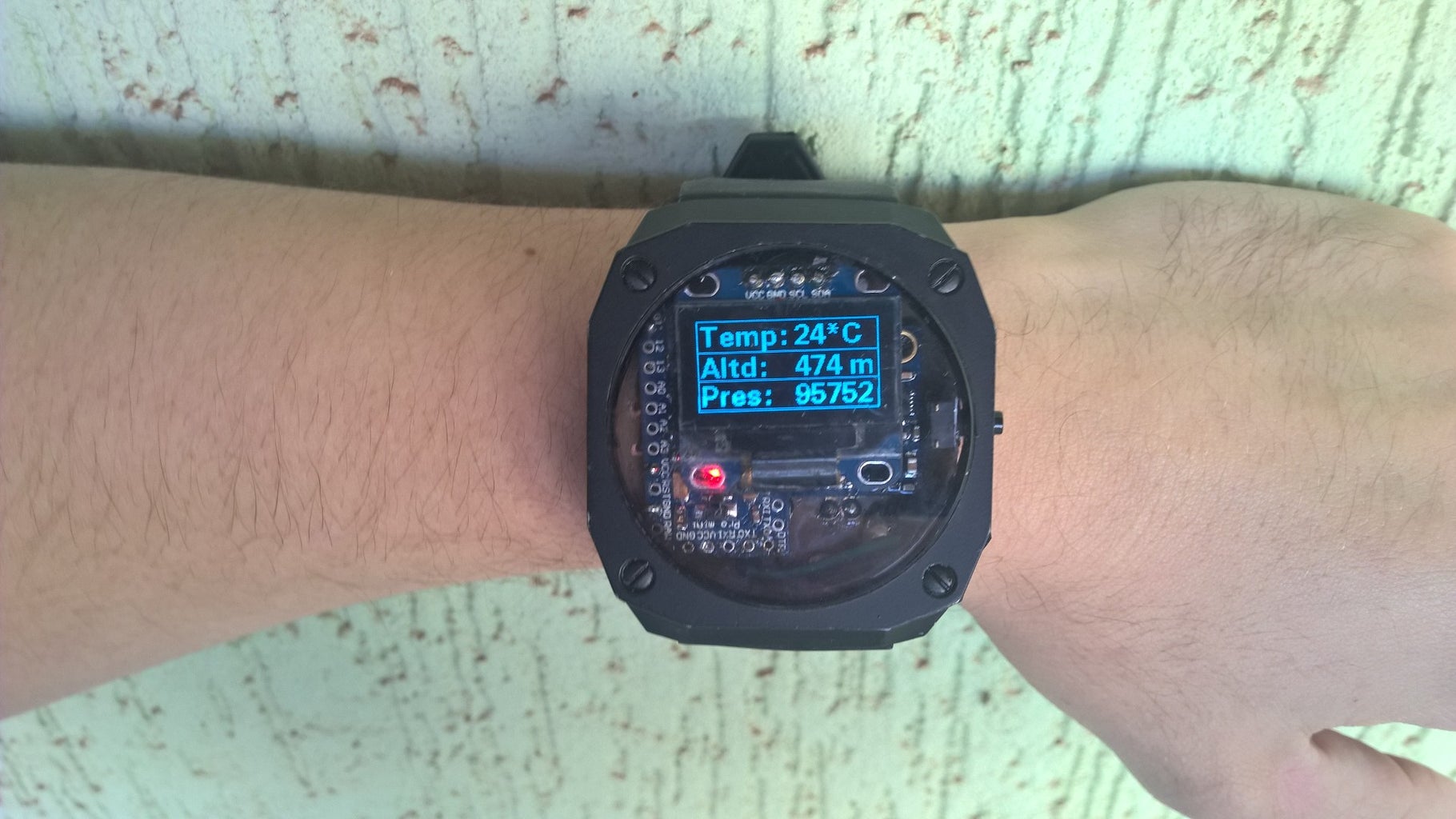
The third version was the first to be one I could use on street and is pictured on this instructable: it is on the last four images. The battery lasts 24 hours easily, and I took out one led from the GY-87 sensors board. I left one led because I forgot to take out, but ended cooler this way. However there are some stuff I can improve on future versions:
- I drilled the hole for the button and for the charging conector too distant one from the other;
- I could have placed the parts better, sparing space;
- I could have designed the pcb on Eagle way better, voiding short circuits;
- I could have programmed better the pedometer;
Next step we assemble the componentes!
UPDATE: the battery lasted 26 hours on regular use.
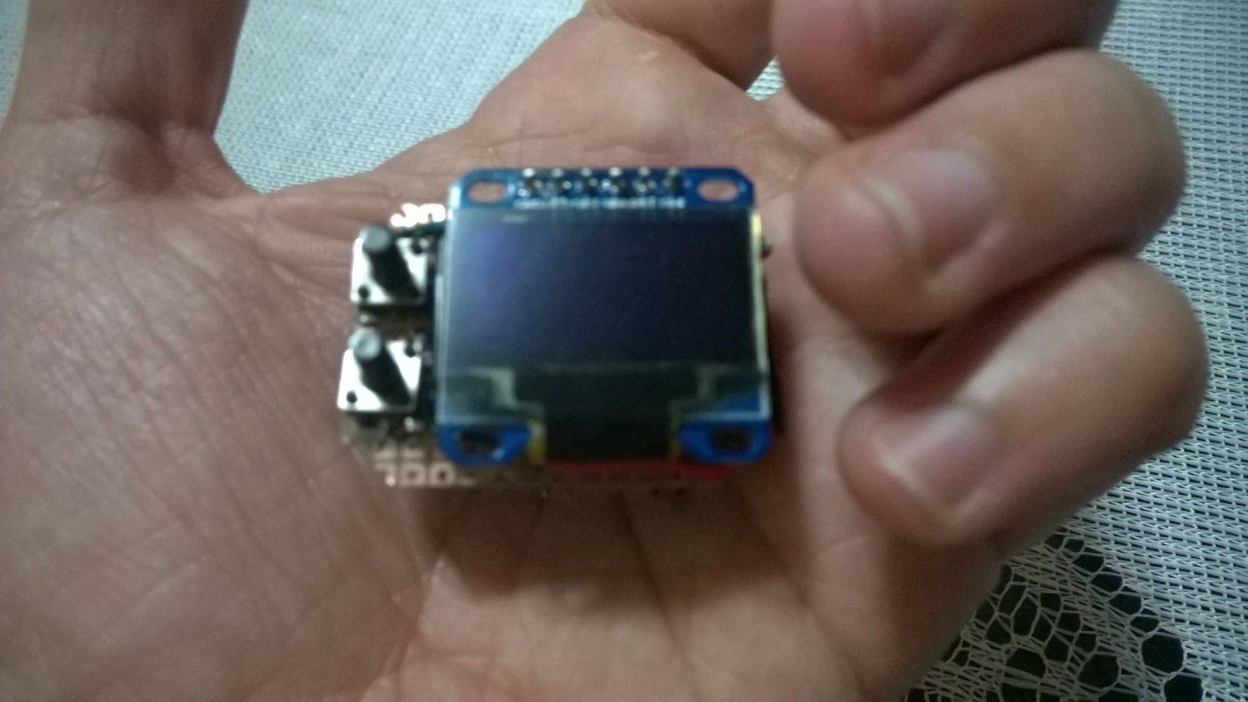
Step 2: The Parts:
- 10DOF sensor (HMC5883L, MPU6050 and BMP180) Ebay (1);
- Arduino Pro Mini 3.3V (or compatible) Ebay (2);
- Cellphone battery (3.7 - 4V);
- I2C Oled Display (blue color) Ebay (3);
- Copper pcb board Ebay (4);
- Ferric chloride Ebay (5);
- DC Female Power connector 2.5mmx0.7mm Ebay (6);
- Tactile switch (side button) Ebay (7);
- An old or cheap watch you can unmount (preferably big enough);
- Solder wire, soldering iron, solder sucker, etc;
- After, of course, you will need the battery charger, wich wont be inside the watch, Ebay (8);
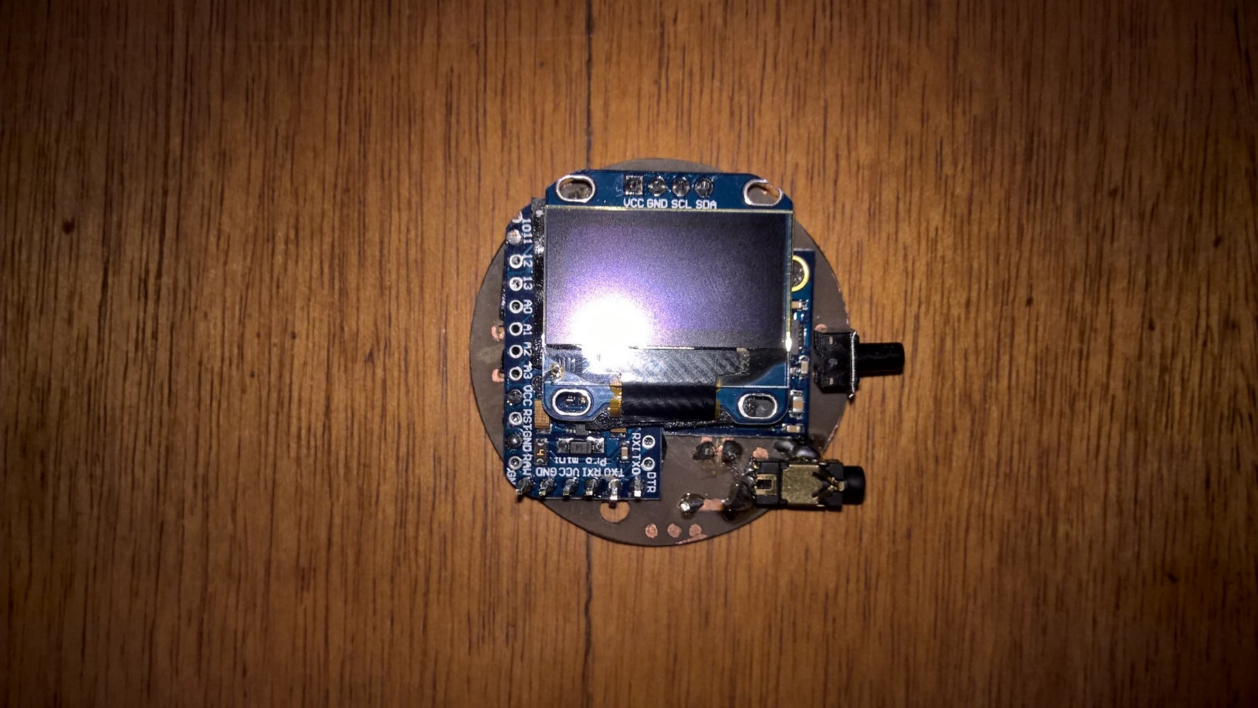
Step 3: Connecting the Parts and Eagle Board:


I included the zip file to my Eagle design, but I advise you that it has mistakes, because I was learning how to use the software at the time. I intend to make a better version on my next try. However, it is really easy to understand how the parts should be connected. It goes as follow:
1- Arduino:
- PIN 2 - Button output;
- VCC - on VCC from the charging connector, VCC of display and sensor;
- GND - GND from charging, button input, and sensors / display GND;
- A5 PIN - on I2C SCL pin from display and sensor;
- A4 PIN - on I2C SDA pin from display and sensor;
2 - Button:
- One pin on GND;
- Other pin on Digital input pin 2 from arduino;
3 - Display:
- VCC pin;
- GND pin;
- SCL pin on arduino A5;
- SDA pin on arduino A4;
4 - GY-87 (sensor board):
- VCC pin on VCC from arduino;
- GND pin;
- SCL pin on arduino A5;
- SDA pin on arduino A4;
- Other pins are not connected! Including the 3.3V VCC, wich wont be used!
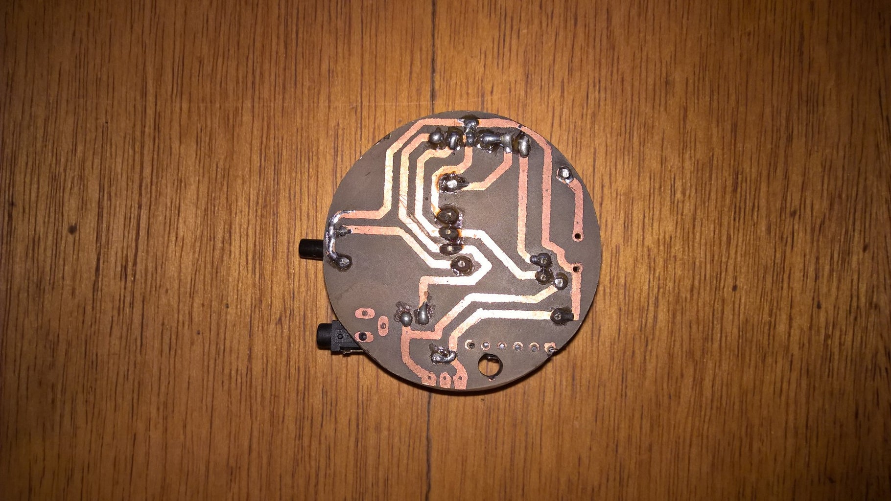
You can now opt to take out both leds, one from the arduino (near the reset button), and the one on the sensors board. Both are useless and consume around 1.5mA each constantly, which we cant afford. Now you have to make your own pcb board with the copper board and ferric chloride. I wont get to details here because there are plenty instructables on this, like this one. In my project I also used a laser printer for better results.

Step 4: The Code:
As written before, I made three versions of the watch. However, the second and third versions are very similar one to the other, so I uploaded here the first and the last versions. The first because had the support to the bluetooth syncronization with the windows phone, having calendar. I also uploaded the code for the windows phone app, with the compass. Hope everything is still working. The libraries I used:
- Wire.h;
- I2Cdev.h (included to download);
- MPU6050.h included in I2Cdev;
- Ug8lib.h (included to download);
- Time.h (included to download);
- HMC5883L.h (included to download);
- Adafruit BMP085.h (also included);
The older version of the watch also used the library:
- SoftwareSerial.h download;
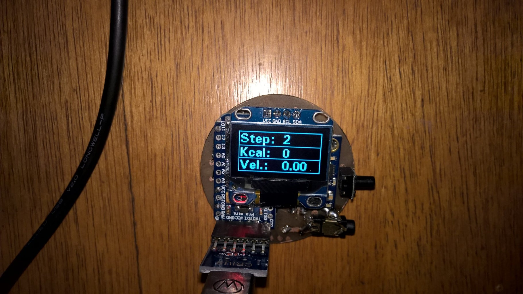
Step 5: The Pedometer:
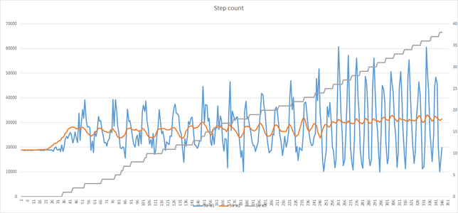


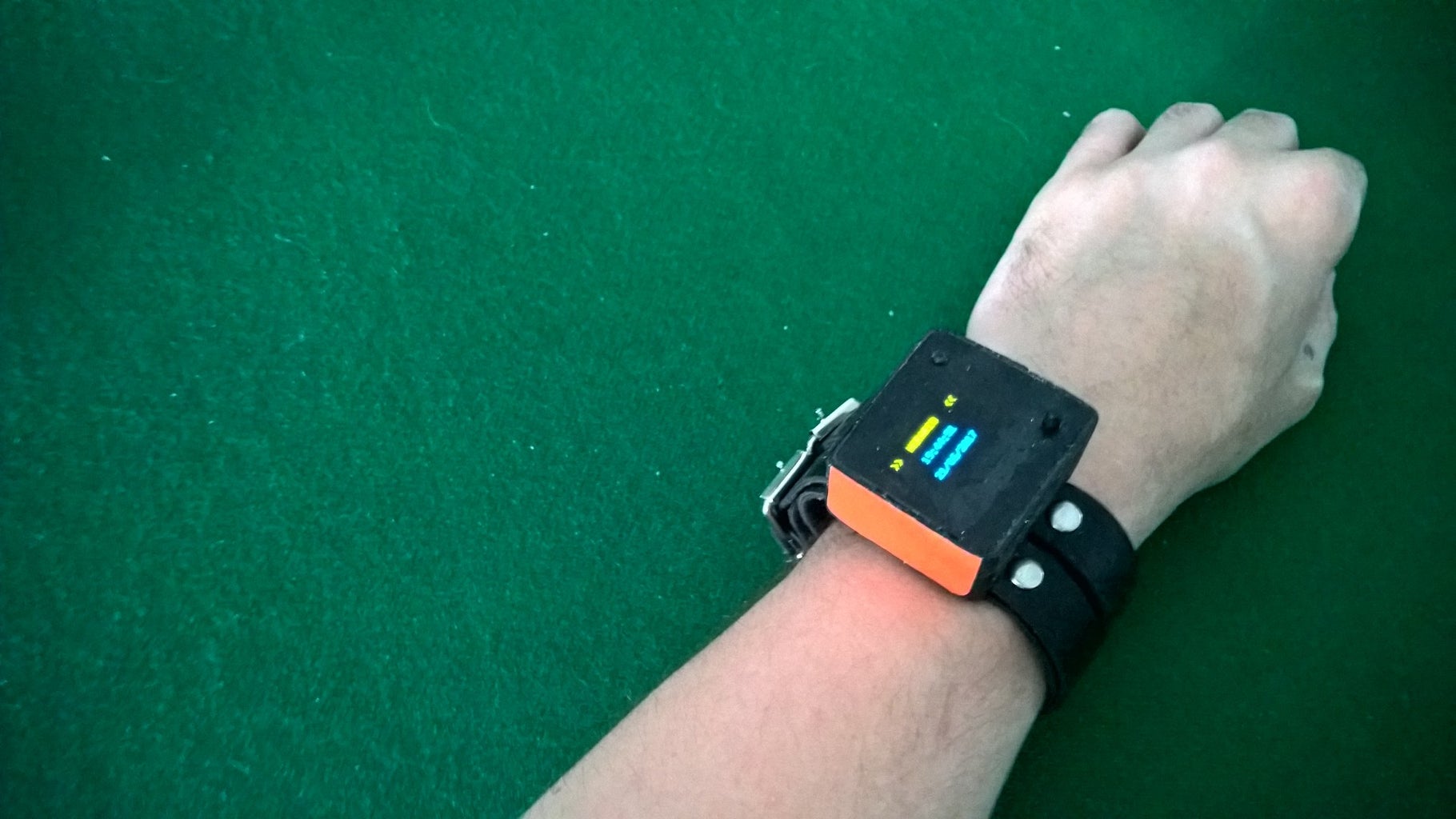
Usually, pedometers are made by calculating the pulse on accelerometers on the Z axis, because the sensor is placed on a belt near the chest of the person. This time, how the watch was on the wrist, it wouldnt make sense reading just the Z value, because the wrist moves in many ways. However, the arm goes forward and backwards when walking or running. So initially I figured out that the sum of the values S = |X|+|Y|+|Z| would increase and decrease on each step. By calculating the moving average of the last N values for S (Av = SUM(S)n/N) and comparing them with the current moment of S I could say: if Sn-1<= Av and Sn>Av then add one step to counter (image 1).
Of course, if you bounce or move your arm, the counter would add a step (false reading). So I added a minimum limit for Av, such as on the image, it could be 22000. Below this would mean you are moving your arm, but not walking. Higher values for Av, such as 30000 mean you are running (easily seen on the image).
After some tests, I discovered that moving the arm had a sum of accelerations really close to walking, so I had to find a way to identify one from the other. I did that by:
- S = |X|+|Y|+|Z| for a given moment;
- SM = the maximum value for S over the last N moments;
- AVM = the moving average of SM for M given iteractions;
- AVM <= 37000 =>doing nothing useful;
- AVM > 37000 ans <50000 =>walking;
- AVM >= 50000 =>running;
The excel file with all my tests is included.
Attachments
Step 6: Conclusion


I hope you guys like it! I pretend to make a better (and final) version of this watch in the near future, improving the pcb, the code, the part calculating the steps to differentiate walking and running from driving a car(this one is hard). And I am open to ideas, so if you think of something cool, please tell me! I could make a better version buying the components and making the board be smd, and solder them individually, but right now I feel it would be really hard and for now I am lazy enough (lol). That stays for a distant future from now. See you in my next instructable. Dont forget to check my other ones!!
Ben Hur Gonçalves.

Participated in the
Outside Contest


