

Introduction: Attiny85 Decision Box V2.0


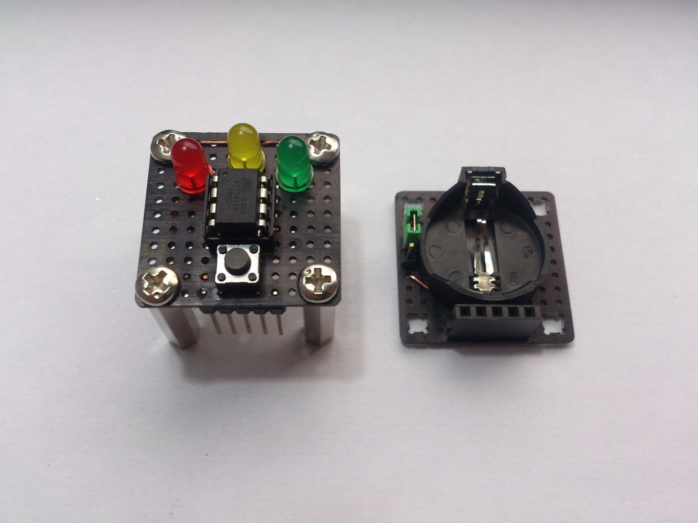
After seeing my first Attiny85 based "Decision box" had become quite popular I decided to make a second version with more improvements using common materials so everyone can build it.
The main difference between the first and second version are the materials they're made of, while the first box was made out of wood, this version has two perforated boards stacked together with hex spacers and screws, and connected by pin headers and connectors. This makes it more modular, robust and easy to assemble. Another difference are the LED's, in this version I used three LEDs instead of a single common cathode red-green LED, not just because I had more space to put them, but also because it has allowed me to be more creative when making the program.
Step 1: Materials:
- Attiny85
- 8pin chip socket
- Coin battery holder
- CR2032 Coin battery
- Perforated board
- Pushbutton
- Hex spacers (around 2cm, 3/4 inch)
- 8 screws for the spacers
- Long pin headers
- Connectors for the pin headers
- Red, green and yellow LEDs
- Copper wire
- 120Ohm resistor
- 10kOhm resistor
You'll also need a soldering iron.
Step 2: The Circuit:

The circuit is quite simple, but assembling it together in two different planes can be a bit tricky.
This circuit runs on 1mA when in idle and around 5-6mA when using the LEDs, so assuming the coin battery has a capacity of 200mAh, it should run for a week before draining the battery in case its left on.
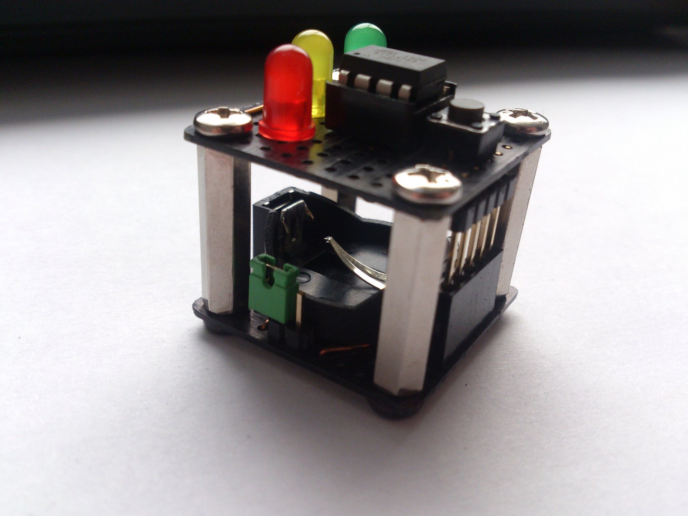
Step 3: Assembling the Cube.

Start by cutting two squares of 11x11 pads, we need an odd number of pads because components like the button occupy an odd number of them, and by making this we make sure they are symmetrical respect to the center line.I also bent the pins of the chip socket so it could fit in a 4x3 group, instead of the usual 4x4, this way it's properly aligned and vertical. You can also connect it in an horizontal way, but making the connections could be harder. If you find hard to do this you can always use a 13x13 boards, or 12x12, if your button occupies 4x4 pads.
Make a hole at the center of the 2x2 pad groups located at the edges, the hex spacers will be placed there, the holes need to be big enough for the screws to fit in. Use a precision tool for better accuracy.
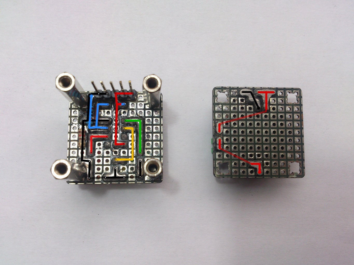
Once the holes are made put the components on the board. I've traced the circuit with colors according to the schematic so you don't get lost when soldering it.
Notice that there is solder under the blue resistor (10kOhms) connecting the LEDs and the chip to ground.
For the main switch I used a a pair of pin headers and a bridge connector from a computer, you can use a small though-hole switch or even a tilt switch.
Step 4: Connectors
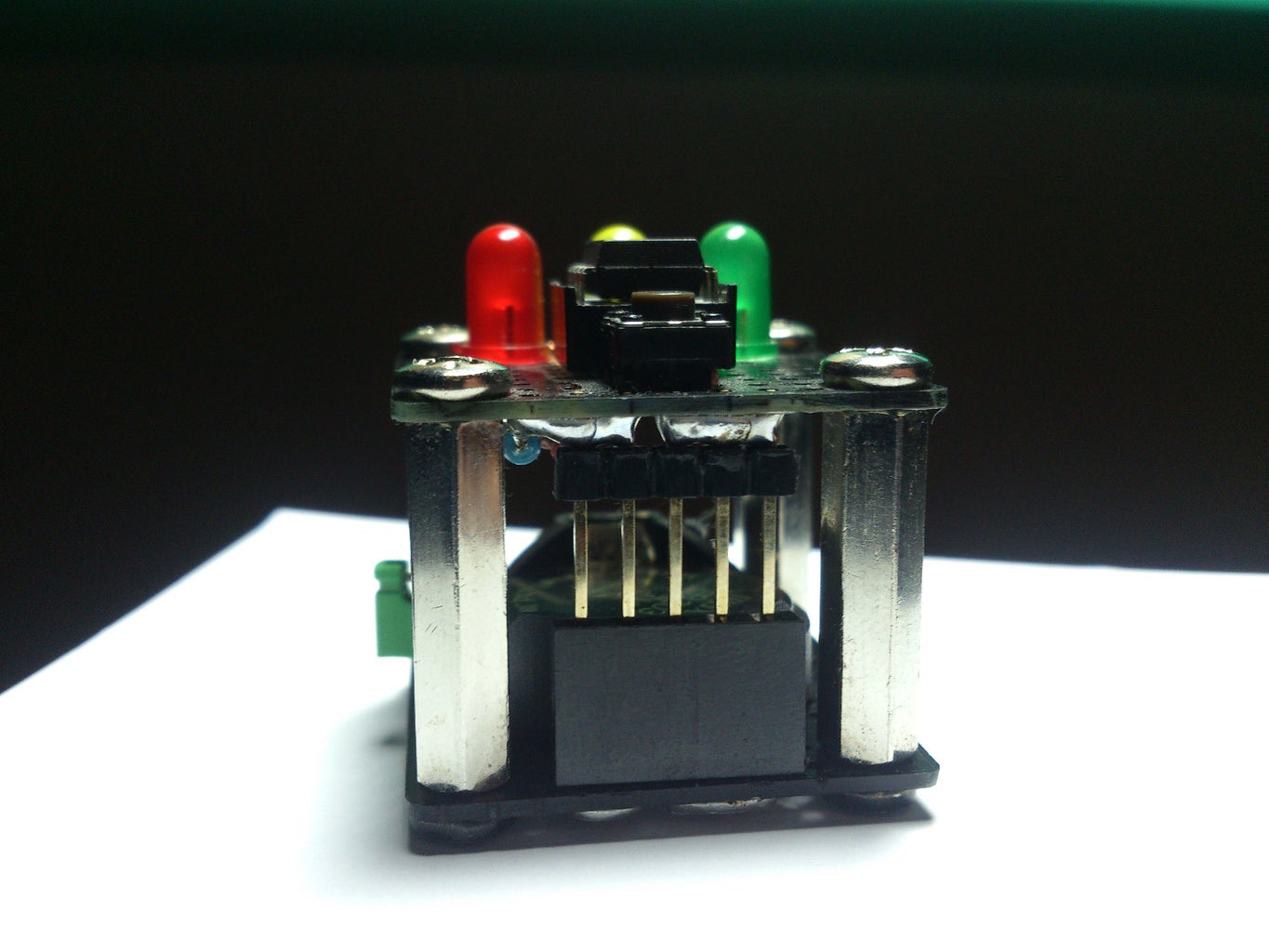
To assemble the pin headers and connectors that will join the two boards, solder a 5 connector row between two hex spacers, using the pads at the edge, remember to separate them into positive and negative. Once the connector is soldered, cut the long pin headers to an appropriate length so they can be fully inserted leaving just a small gap between the plastic holding the pins together and the upper board, then solder them as shown in the picture. It's quite tricky, but I haven't found any other way to overcome this.
Step 5: Uploading the Code
As always remember that to upload the code to your Attiny85 you must go to >Tools>Programmer>Arduino as ISP and Tools>Boards>Attiny85 1MHz clock.
You can check other instructables on how to program an attiny85 if you haven't worked with them yet.
I strongly recommend you to visit nqtronix's instructable, since he offered to re-do the program with power saving modes and it also contains many and very useful information like program optimization.
You can also check gmiller6's program, he changed the display mode of the random function.
Attachments

Step 6: Customization and Probabilities

The yellow LED, which wasn't enabled in the previous version, can now be used, and interpreted as a "maybe". This can be undone changing the program and removing the LED, you could even add a button pattern recognition function or an extra button to disable and enable it.
You can also change the probabilities, for example, you can set red and green (no and yes) to 40%, and keep the yellow (maybe) at 20%. To do this, simply expand the range of the elements in the random function and include them in the statements as shown as shown in the picture.
The random function will output anything from 0 to the second variable minus 1, meaning that if we introduce 3, the results can be 0, 1, or 2 (red, yellow, green). By introducing 5 as the second variable we can get 0, 1, 2, 3 or 4. We can use an "if" function so 0 or 1 are recognized as red (40% chance), 2 yellow (20% chance) and 3 or 4 green (40% chance).
To compare two variables at a time you can use " || " (Alt+124), this is OR, and means that if one OR the other occurs, the statements will be executed.
Step 7: ???

Since easter is just around the corner I've added an easter egg to the program. And of course I won't reveal what it is or does, if you want to find out you'll have to build the circuit, you could also analyze the program, but that would be cheating. I'll just say this easter egg is quite more elaborated than the random part itself, and you'll probably end using it more too.
Step 8: Thanks for Watching!

![Tim's Mechanical Spider Leg [LU9685-20CU]](https://content.instructables.com/FFB/5R4I/LVKZ6G6R/FFB5R4ILVKZ6G6R.png?auto=webp&crop=1.2%3A1&frame=1&width=306)


