

Introduction: Arduino Thumbstick Controller


In this project I will help you to put together a simple and from scratch Arduino thumbstick controller, to control your projects (servos & DC motors). This is a simple guide to help out new Arduino users on their projects but requires a little soldering (no skill needed). This Instructurable is way simple and it will give other Arduino users ideas on how to make it more clean and better.This was taken from my other Arduino Robotic Arm Instructurable. In other words it is just to guide you on your future projects. "USE YOUR IMAGINATION". I don't make my Arduino stuff permanent I always reuse them and it is just for prototyping. Like always I hope to help you again with this one and leave comments on more ideas ....enjoy!!!... BI()ME(H75
Step 1: Materials

Most of the materials were bought @ RADIOSHACK
Arduino Uno X1
Bread board X1
Servo Motors X4
Parallax thumbsticks X2
Prototiping wires (see the pic) X around 26 of them
Hot Glue Gun X1
Dreamel tool (or similar one) X1
A plastic school supplies box X1
Step 2: Plastic Box


Before soldering, look where are you going to place everything. I got lucky because when I saw this particular box I was thinking where everything were gonna be place. Go to Wal....... or any other place and shop for the box, mine cost me $1.29. I use tape to temporally tape most of it where i wanted to be. Then I cut the holes with the dreamel tool. The cuts are not clean but they will do for project.
The Arduino board, bread board, and thumsticks.
Step 3: Soldering


In this part we will do some soldering. You don't need any skill for this only "patience".
We will connect together the joystick connections in pairs so they can communicate better with the Arduino. (this way is better than on my other instructurable "The Robotic Arm"
Solder everything an double check all the connections!!!
Follow the pictures
Step 4: Connections


WARNING!!! Always double check your connections specially if you did some soldering.
Follow the pictures for all the connections. ( I have took them from my Arduino Robotic Arm Instructurable)
Joy_1 Right side:
L/R+ and U/R+ is the 5V Arduino connection (power)
GND and GND is for ground on the arduino L/R and L/R goes to the Arduino ANALOG connection A4 U/D and U/D goes to the Arduino ANALOG connection A3
JOy_2 Left side:
L/R+ and U/R+ is the 5V Arduino connection (power)
GND and GND is for ground on the arduino L/R and L/R goes to the Arduino ANALOG connection A2 U/D and U/D goes to the Arduino ANALOG connection A5
Servos 1 & 2:
Servo 1 connections: Red wire: Arduino 5V, Black wire: Arduino GND, Yellow wire: Arduino Digital PWM 10
Servo 2 connections: Red wire: Arduino 5V, Black wire: Arduino GND, Yellow wire: Arduino Digital PWM 11
Before any assembly test the connections with the servos. If double check is complete then follow the next step
Step 5: Assembly

WARNING!!! Before you put everything together DOUBLE CHECK all the SOLDERING and CONNECTIONSSS!!!
Here we will put everything together as you see on the picture
Notice that you can even fit an 9 volt battery to power the Arduino
Step 6: CODE
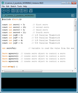
#include
const int servo1 = 3; // first servo const int servo2 = 10; // second servo const int servo3 = 5; // third servo const int servo4 = 11; // fourth servo const int joyH = 2; // L/R Parallax Thumbstick const int joyV = 3; // U/D Parallax Thumbstick const int joyX = 4; // L/R Parallax Thumbstick const int joyP = 5; // U/D Parallax Thumbstick int servoVal; // variable to read the value from the analog pin Servo myservo1; // create servo object to control a servo Servo myservo2; // create servo object to control a servo Servo myservo3; // create servo object to control a servo Servo myservo4; // create servo object to control a servo void setup() { // Servo myservo1.attach(servo1); // attaches the servo myservo2.attach(servo2); // attaches the servo myservo3.attach(servo3); // attaches the servo myservo4.attach(servo4); // attaches the servo // Inizialize Serial Serial.begin(9600); } void loop(){ // Display Joystick values using the serial monitor outputJoystick(); // Read the horizontal joystick value (value between 0 and 1023) servoVal = analogRead(joyH); servoVal = map(servoVal, 0, 1023, 0, 180); // scale it to use it with the servo (result between 0 and 180) myservo2.write(servoVal); // sets the servo position according to the scaled value // Read the horizontal joystick value (value between 0 and 1023) servoVal = analogRead(joyV); servoVal = map(servoVal, 0, 1023, 70, 180); // scale it to use it with the servo (result between 70 and 180) myservo1.write(servoVal); // sets the servo position according to the scaled value delay(15); // waits for the servo to get there // Read the horizontal joystick value (value between 0 and 1023) servoVal = analogRead(joyP); servoVal = map(servoVal, 0, 1023, 70, 180); // scale it to use it with the servo (result between 70 and 180) myservo4.write(servoVal); // sets the servo position according to the scaled value delay(15); // waits for the servo to get there // Read the horizontal joystick value (value between 0 and 1023) servoVal = analogRead(joyX); servoVal = map(servoVal, 0, 1023, 70, 180); // scale it to use it with the servo (result between 70 and 180) myservo3.write(servoVal); // sets the servo position according to the scaled value delay(15); // waits for the servo to get there } /** * Display joystick values */ void outputJoystick(){ Serial.print(analogRead(joyH)); Serial.print ("---"); Serial.print(analogRead(joyV)); Serial.println ("----------------"); Serial.print(analogRead(joyP)); Serial.println ("----------------"); Serial.print(analogRead(joyX)); Serial.println ("----------------"); }
Attachments

Step 7: Troubleshooting

Q1. The servos won't move.
Answer: Check the connections, remember in this tutorial we use PWM pins for the servos and the ANALOG pins for the joysticks.
Q2. When I upload the code to the board the servos, they start vibrating.
Answer: It means that either U/D+ or L/R+ connections and soldering are touching not properly connected. Double check your connections. You have to disconnect the usb from the board to verify connections.
Q3. There is a vibration from one of the servos.
Answer: This happens because of the combination of micro servos and standard servos. (I did this project with 4 Parallax standard servos with no vibration issues at all). The micro servos used in here are the cheap ones from Ebay.
DOUBLE CHECK THE SOLDERING!!!!!!
Step 8: Final Product


Final thoughts on the final product.....
Future additions: A middle joystick or potentiometer.
easy female connections in the front for the servos.
Instead of Arduino Uno.... the use of the Arduino Nano 3.0 ( not many servos and no DC motor) Use your imagination


