

Introduction: Assembly Language Blinking Lights for a PIC16


I believe that it's a right-of-passage for every Electrical Engineer and Computer Scientist to do at least some assembly language programming. The reason being that assembly language programming brings you very close to the metal on a microcontroller and helps you truly understand the system architecture of a chip and what's going on. The PIC16 range of microcontrollers are a very good starting point for learning some assembly language for the simple reason that there's only 35 instructions to learn. Compare this to an ATMega328p where there's 131 instructions to learn. This makes the PIC16 a great place to start learning assembly language programming. This tutorial will give you all the basics of getting 8 LED's blinking on and off with a PIC16F690 micro controller. The lessons learnt in this tutorial can be applied to other PIC micro controllers and micro controllers in general.
Supplies

Because I wanted to build a real circuit and not just a simulation you will need some materials and tools to do this project, here's what I used:
Materials:
- PIC16F690 Microcontroller x 1
- Small breadboard x 1
- Green LED's x 4
- Red LED's x 4
- 220 ohm Resistors x 8
- Short Jumper Wires (male/male) x 10
Tools:
- PICkit2 Programmer
- Programmer Adaptor
- PICkit2 leads
- 3.5 to 5V DC power supply or battery
- Laptop or PC
You don't have to use the PICkit2 programmer, you could use the PICkit3 or other programmer. The PICkit2 is cheap, easily available on ebay and is easy to use.
Step 1: Build the Circuit


It was a difficult decision to decide whether to have the Circuit as Step 1 or the Program as step 1 as you need to understand the program to build the circuit and you need to understand the circuit to write the program. I guess it's just an iterative process and you just have to jump in a start somewhere.
Whichever you choose to do first you really need to read the data sheet. The aim of this project is to blink 8 LED's with 4 Red LED's on and 4 Green LED's off and then 4 Red LED's off and 4 Green LED's on continuously swapping over. The first thing we need to establish is where on the micro controller we need to connect the LED's.
From the Data Sheet we can see on the pinout description that Pins RC0 to RC7 are all general purpose I/O pins (Input/Output) which meaning we can use them to drive the 8 LED's. Secondly looking at the pinot of the chip we can see that they are connected to the following pin numbers:
- RC0 = pin 16
- RC1 = pin 15
- RC2 = pin 14
- RC3 = pin 7
- RC4 = pin6
- RC5 = pin 5
- RC6 = pin 8
- RC7 = pin 9
This means we can connect green LED's to pins 16, 14, 6 and 8 then red LED's to pins 15, 7, 5 and 9. This will give us alternating flashing LED's. I will explain more later.
From the Data Sheet on the block diagram we can see that all these pins are on Port C and then on the description of the special function registers that Port C is at memory address 0x07h (this is a hexadecimal number, which in this case is actually the same as 7 in normal decimal numbers.
From the pinout we can also see that the power supply positive voltage (3.5 to 5V) is connected to pin 1(VDD) and the ground connection (0V) is connected to pin 20 (Vss)
A copy of the full data sheet is attached.
Attachments

Step 2: Coding Some Assembly

In this step I'm going to walk through the program one stage at a time.
The fist thing to point out is that anything after a semi colon ";" is a comment is ignored when the code is assembled.
; Blink 8 LED's on Register on PORT C
We next declare what processor we are using with
#include <p16F690.inc>
This brings in an include file which defines all the special function registers in the microcontroller and also all the memory available on the microcontroller, in this case the PI16F690.
The next stage of the program is to configure the chosen microcontroller, to do this we declare a configuration word as shown below. I'm going to go through this in detail as this can be quite confusing to those who have come from the Arduino environment as this stage is hidden and done automatically. Moving away from Arduino gives you the freedom to change the configuration of your microprocessor.
__config (_INTRC_OSC_NOCLKOUT & _WDT_OFF & _PWRTE_OFF & _MCLRE_OFF & _CP_OFF &_BOD_OFF & _IESO_OFF & _FCMEN_OFF)
The "_config" just says that the following code is part of the configuration word. It's quite hard to get your head around the meaning of the configuration word so I'm going to break it down.
_INTRC_OSC_NOCLKOUT - This part of the word defines the clock source we are going to use, in this case it is the internal 8MHz Oscillator which is set at 4MHz as standard through a pre-scaler (divides it by 2) with no clock output. If you wanted to use an external crystal Oscillator you would change this to be _HS_OSC.
_WDT_OFF - This tells us if we want to use the watchdog timer. It checks to see if the software or hardware is running ok. If it's not it automatically resets the micro controller. We are not using it but to turn it on change the code to _WDT_ON.
_PWRTE_OFF - This is the Power-up Timer Enable bit and allows the supply voltage of the microcontroller to rise to an acceptable level before operating.
_MCLRE_OFF - Pin 4 on the PIC16F690 can be used as the reset pin, in our case it is not being used as the reset pin so it is internally connect to VDD (the supply voltage) and the pin can then be used for other things. If this is changed _MCLRE_ON the pin can be used to reset the PIC16F690 when you connect it to ground. I'm going to try this later.
_CP_OFF - This prevents unauthorised access to the program memory, it protects your code. In this case we have no code protection however you can protect all or some of your code by changing it to _CP_ALL or _CP_50 Code protection is a good reason you don't use "out of the box" Arduino for commercial projects.
_BOD_OFF - Brown out detection is a form of protection in the microcontroller detecting when the supply voltage goes below a level for reliable operation. Brown out Detection monitors the voltage level and puts the device into a reset state to ensure proper start-up when power returns. In this case it's turned off but to turn it on change it to _BOD_ON.
_IESO_OFF - This allows the device to switch from internal and external clocks, in this case it's switched off.
_FCMEN_OFF - This setting allows the system to automatically switch over to one of the internal clock modes if an external clock source fails in this case it's switched off.
There are other snippets available that I have not used such as _DP_OFF or _DP_ON. This would enable the protection of the data in the internal EEPROM.
The next line of code
org 0
This simply tells the assembler where to start generating code.
We then setup some "sort of" variables as follows:
		Delay1 		equ 21h
		Delay2 		equ 22h
These to lines setup an instruction to the assembler to replace every occurrence of the word "Delay1" and "Delay2" in in the code with the values 21hex and 22hex (memory locations). This will then be used in the delay subroutines.
The next section of code is given the label "Start" and is similar to the "Void setup ()" function in an Arduino program.
	Start
	BSF STATUS, RP0 ; select Register Page 1 (RP)
	CLRF TRISC ; make I/O PORTC all output
	BCF STATUS, RP0 ; back to Register Page 0
The purpose of this block of code is to set the pins on Port C to outputs. Because the memory in the PIC16F690 is arranged in four banks (Bank 0, Bank 1, Bank 2 and Bank 3) we have to enter the bank containing the memory we want to change before we change it. To make all of the pins on Port C to outputs we need to make all of the bits in the data direction register TRISC a "0". First we need to enter the memory bank containing TRISC which can be found in the data sheet and is in Bank 1. To get into Bank 1 RP1 needs to be "0" and RP0 needs to be "1". RP1 is already a "0" so we don't need to change it. So the first line uses BSF to set RP0 to "1", it is "setting the bit" (Setting means making the value a "1"). The instruction CLRF TRISC then clears all the bits in the TRISC data direction register therefore making them all 0's and therefore outputs (Clearing means making the value a "0"). The final line BCF then clears RP0 making it "0" again so that we are back in memory bank 0, RP1 and RP0 and both now set to "0".
The next section of the program begins the MainLoop, this is similar to the "void loop ()" in Arduino.
	MainLoop
	MOVLW 0x55 ; put ‘0101 0101’ ie 8 in the working register (hex 55 or dec 85)
	MOVWF PORTC ; Copy the Wreg to Port C (to the LEDs)
On the PIC16F690 nearly all data has to go through the working register "W". MOVLW 0x55 puts the hex value of 55 into the working register ready to move it to somewhere else. Hexadecimal 55 is the same as binary ‘0101 0101’ therefore ready to turn on every other LED on when this data is moved to Port C. The instruction MOVWF PORTC simply puts our data in the working register into Port C.
We know have every other LED on so we need to include a delay before we urn them off and turn on the other four LED's. The following code creates a delay.
	OndelayLoop ; Delay 0.2 Sec subroutine, depends on the clock source used, faster clock means less delay
	DECFSZ Delay1, f ; Decrement file register, skip next instruction if zero
	GOTO OndelayLoop ; Repeat loop if Delay1 is not zero
	DECFSZ Delay2, f ; Decrement file register, skip next instruction if zero
	GOTO OndelayLoop ; Repeat loop if Delay2 is not zero
As the comment says, this block of code with the label "OndelayLoop" creates a 0.2 second delay. This section of code uses Delay1 and Delay2 as defined earlier. These memory locations each holds a value between 0 and 255 the instruction "DECFSZ Delay1, f" causes the value in the memory address Delay1 to decrement by one each time this line is accessed and then skip the next instruction when the value hits zero. If the value in the memory address Delay1 (memory address 21) is not zero the the instruction "GOTO OndelayLoop" is run which causes the program not to go to the next line and go back to the start of this subroutine. For example if the value is decremented from 255 to 254 then it is not zero so the program doesn't go to the next line but goes back up to the beginning of the subroutine which repeats (next decrementing to 253) until the value of Delay 1 is 0. When Delay1 reaches 0 the next line is run "DECFSZ Delay2" which does the same as the last but if it is not 0 it means it then has to go to the start of the subroutine again which also means it has to decrement Delay1 all over again. This means that you need to decrement Delay1 to 255 over and over again 255 times (5709 operations).
To get another 0.2 second delay we run this same code again, but with the new label Onedelayloop1, before we change the LED's connected to PORT C as below.
	OndelayLoop1 ; Repeat delay sub routine to get another 0.2 Sec delay
	DECFSZ Delay1, f ; Decrement file register, skip next instruction if zero
	GOTO OndelayLoop1 ; Repeat loop if Delay1 is not zero
	DECFSZ Delay2, f ; Decrement file register, skip next instruction if zero
	GOTO OndelayLoop1 ; Repeat loop if Delay2 is not zero
The next line of code turns off the LED's currently on and turns on the other LED's connected to PORT C.
	MOVLW 0xAA ; put ‘1010 1010’ ie 8 in the working register (hex AA or dec 170)
	MOVWF PORTC ; Copy the Wreg to Port C (to the LEDs)
This is the same as we did before just using the hexadecimal value of AA binary (1010 1010).
Next we add another delay but only using a single delay subroutine (labelled OndelayLoop2) so that the LED's are flashing asymmetrically. I did this so that we can see where we are in the program when everything is connected.
	OndelayLoop2 ; Repeat delay sub routine to get another 0.2 Sec delay
	DECFSZ Delay1, f ; Decrement file register, skip next instruction if zero
	GOTO OndelayLoop2 ; Repeat loop if Delay1 is not zero
	DECFSZ Delay2, f ; Decrement file register, skip next instruction if zero
	GOTO OndelayLoop2 ; Repeat loop if Delay2 is not zero
The final section of the program is.
	GOTO MainLoop
	End
"GOTO MainLoop" simply causes the microcontroller to go straight back to the start of the MainLoop causing the LED's to swap over at the start of this subroutine. As you can see, the MainLoop just keeps repeating over and over again and the program never actually gets to End.
I have attached a text file with the program, you can edit the text in any text editor but you will need to ensure the spaces are all correct for the program to run.
Attachments

Step 3: Building Your Hex File


The first thing you need to do is download the MPLAB IDE (integrated development environment) onto your computer. I am using version 8.92 which you can download from the Microchip archives with the following link: MPLAB® Ecosystem Downloads Archive | Microchip Technology.
Now follow these steps and look at the pictures to show the process:
- Select what Microcontroller you are using by clicking the MPLAB configure menu and then Click Select Device. This will open a window with a dropdown menu for device, if you are using the PIC16F690 then select this device.
- Bring you program into MPLAB by Clicking File then New. This will open up a new workspace where you can either copy and paste your program or type it in. It will just be plain black text at this point. The next stage is to save it as an Assembly Language File in the appropriate folder with the file extension .asm. This will change the program into different coloured text, such as blue for mnemonics etc. You can now close this file.
- Next we are going to create a project using the Project Wizard. Click Project then Project Wizard and a Project Wizard Window will open.
- Click Next then select the device you are using with the drop down menu, the PIC16F690.
- Click Next again and create a new project folder in a location of your choice.
- The next stage is to add your assembly program to your project. On the left of the window there will be a list of available files. Click on the one you want the click ADD and it will enter into the empty box on the right. Then click on the large capital letter to the left of your file and keep clicking it until it becomes a "C".
- Click Next and then Click Finish.
- You are now ready to build your HEX File
- A window will be open that contains your project. Click Project then in the menu Click Build All.
- A window will open asking you to Click "Absolute" or "Relocatable". Click Relocatable.
- The project will now build and hopefully you will have a message saying "BUILD SUCEEDED".
If your build fails it is most likely to be because of an error in your prog, you through your program and check spacings, spellings of Labels and mnemonics et..
Step 4: Simulating the Program


With MPLAB you can run your code in a simulator to check what's happening. In our case we will be able to see the value in the memory address of PORT C changing from "10101010" to "01010101" over and over again. To Simulate your project follow these steps, see the pictures for a guide:
- Click the Debugger Menu, Then Select Tool and select MPLAB SIM.
- Click View then File Registers and a window simulating your registers will appear.
- In the toolbars there is a series of buttons, one of which has two turquois arrows, click this button and you will see your program appear and the registers in the memory window start changing as it goes through the program.
- You can speed up your simulation by Clicking Debugger then settings then Click the Animation / Realtime Updates Tab and moving the Slide bar across to the left.
- There are also other buttons that allow you to step through your program one line at a time, you will need to halt your program first before using these buttons.
Because of the delay subroutines it will take ages for the program to run in the simulator. If you want to see it run faster you can comment out the delays and run it so you can see the registers change.
The video shows the full build and simulation process.
Step 5: Uploading to the PIC16F690 and Testing


Now we've built our circuit, written a program, built it and simulated it must be time to upload it to the microcontroller. Here's the steps to get the program running on the microcontroller:
- First make sure you are in your project, you should already be from the last step.
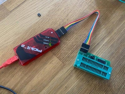
- Connect the PICkit2 to the programmer adaptor with the 6 wires. The pin with the arrow going to it goes to VPP on the programmer adaptor.
- Plug the USB lead into the programmer adaptor and then into your computer.
- In MPLAB select programmer then PICkit2 from the dropdown menu. The PICkit2 will connect and you will get a ready confirmation in the output window.
- Place the PIC16F690 in the ZIF socket of the programmer and push down the lever. The PIC16F690 is connected with pins 10 and 11 at the back of the socket.
- Select Programmer again and press program.
- You will get a message in the output window telling you that you have programmed the target.
You can know put the PIC16F690 onto the breadboard and test it out.
The video shows the programming process and the circuit in operation.
Step 6: Summary and Modification
I hope you enjoyed reading this Instructable and more importantly I hope you've learned something and feel inspired to try some assembly language programming.
As I have mentioned, I wanted to try the project using an external oscillator and changing the configuration word accordingly. Have a look at the vide to see the result.


